
Turn on suggestions
Auto-suggest helps you quickly narrow down your search results by suggesting possible matches as you type.
Showing results for
Please log in to access translation
Turn on suggestions
Auto-suggest helps you quickly narrow down your search results by suggesting possible matches as you type.
Showing results for
Community Tip - Did you get an answer that solved your problem? Please mark it as an Accepted Solution so others with the same problem can find the answer easily. X
- Community
- Creo+ and Creo Parametric
- System Administration, Installation, and Licensing topics
- Using Fasteners - Creo Simulate
Translate the entire conversation x
Please log in to access translation
Options
- Subscribe to RSS Feed
- Mark Topic as New
- Mark Topic as Read
- Float this Topic for Current User
- Bookmark
- Subscribe
- Mute
- Printer Friendly Page
Using Fasteners - Creo Simulate
May 06, 2014
08:35 PM
- Mark as New
- Bookmark
- Subscribe
- Mute
- Subscribe to RSS Feed
- Permalink
- Notify Moderator
Please log in to access translation
May 06, 2014
08:35 PM
Using Fasteners - Creo Simulate
I was studying about the use of fasteners (adding them directly with the software tool) in Creo Simulate 2.0 and I couldn't find some answers for the doubts below:
- Simulate 2.0 really doesn't consider the friction between the two parts?
- To size the fasteners, would be correct to consider only the Total Shear Force (from automatic measures). I know this isn't a pure FEA doubt, but I would appreciate help from people with more experience in this matter;
- I setup, in the "Model Setup", all the interfaces to be as CONTACT and then I did two runs, changing the flag "frictionless surfaces" (in the fasteners tool) and the result didn't change. Was it due to the configuration of the "Model Setup" or a limitation of the simulate fasteners analysis (mentioned in the first marker);
- Is it possible to use the PATTERN TOOL for the application of the fasteners or it’s necessary to add one by one.
Could anyone help me please?
Best Regards,
Guilherme
This thread is inactive and closed by the PTC Community Management Team. If you would like to provide a reply and re-open this thread, please notify the moderator and reference the thread. You may also use "Start a topic" button to ask a new question. Please be sure to include what version of the PTC product you are using so another community member knowledgeable about your version may be able to assist.
Labels:
- Labels:
-
General
5 REPLIES 5
May 07, 2014
10:58 AM
- Mark as New
- Bookmark
- Subscribe
- Mute
- Subscribe to RSS Feed
- Permalink
- Notify Moderator
Please log in to access translation
May 07, 2014
10:58 AM
Hi Guilherme,
Thank you for your question.
Let me try to answer your questions.
In Creo Simulate 2.0, we have two forms of contact interfaces - Frictionless or Infinite Friction. In Creo 3.0 we are introducing Finite Friction where you can define the Static and Dynamic coefficient of Friction between components or surfaces.
Let me try to provide details on fasteners. While Fasteners have been available for a number of releases, they were significantly enhanced in Creo 2.0 to properly define the various conditions.
In WF4 all fasteners used a spring idealization to model the bolt/screw. This type of idealization uses a 6x6 stiffness matrix enabled us to calculate the axial forces only, it did not account for any shear or bending forces (these are not defined in a spring). In Creo 2.0 we removed the spring idealization and replaced with a Thimoshenko beam which uses a 12x12 stiffness matrix. This enabled us to calculate the axial forces, as well as, shear and bending forces. The results defined in Creo 2.0 are the most accurate. As the underlying idealization for the fastener better represents the condition. Along with the additional forces captured, the increased stiffness matrix provides more accurate results.
You mentioned you changed the Model Setup to reference all the interfaces to be CONTACT. I would typically maintain the default as Bonded. When you place a fastener, you have a choice of how you want the two components to be contacted as a result of the fastener. Within the Fastener dialog, you can select FIX SEPARATION.
Fix Separation controls the interface (stiff distributed spring) between the two contacting surfaces in the model between the fastener with an outer diameter defined in the dialog as the Separation Test Diameter.
You can also choose to check the Frictionless Interface check box in the dialog. If you select Frictionless Interface, the tangential stiffness of the distributed spring between the contact regions is 0. If you clear the Frictionless Interface check box, the tangential stiffness of the distributed spring between the contact interfaces has a very large value.
Now you can choose to ignore the Fix Separation and manually create a contact Interface between the two surfaces (between the two parts connected by the fastener). I would create a surface region first on both parts around the area you are placing the fastener. I would use those surface region to define the Interface with Contact. It is there where you can define the friction as either none or infinite. Note: In Creo 3.0 you can define Finite. If you select Infinite, you can select to create slippage indicators and define the coefficient of friction to be used for the indicators.
Rule of thumb when using either fix separation on manual contact interfaces.
- Manual contact interface is more accurate (but expensive) then setting the ‘Fix Separation’ ON. (Setting ‘Fix Separation’ to ON, results in a linearized contact interface, whereas the manual contact interface is a nonlinear one).
- Fix Separation works fine as long as there is a good amount (say 90%) of the compression at the interface. So, the workflow should be as follows.
- Set the ‘Fix Separation’ ON. If there are warnings in the RPT file (saying that the Fix Separation is not working as expected), then use the real contact interface.
Lastly, the Pattern capability is not supported in Creo Simulate for placing fasteners. This is an enhancement request we have received and are exploring this option in the future.
Hope this helps.
Regards,
Mark
May 07, 2014
11:24 AM
- Mark as New
- Bookmark
- Subscribe
- Mute
- Subscribe to RSS Feed
- Permalink
- Notify Moderator
Please log in to access translation
May 07, 2014
11:24 AM
Hello Luiz,
Thank you for this question.
Hello Mark,
Thank you for this very detailed explanation.
But would it be possible to have a demo file, for example in the knowledge base of PTC.
So that we can do tests and tests to understand the function.
Cordially.
Denis.
May 13, 2014
09:52 AM
- Mark as New
- Bookmark
- Subscribe
- Mute
- Subscribe to RSS Feed
- Permalink
- Notify Moderator
Please log in to access translation
May 13, 2014
09:52 AM
Hi Mark,
thank you very much for all the clarifications.
Best regards,
Guilherme
May 13, 2014
10:12 AM
- Mark as New
- Bookmark
- Subscribe
- Mute
- Subscribe to RSS Feed
- Permalink
- Notify Moderator
Please log in to access translation
May 13, 2014
10:12 AM
My pleasure Guilherme. If you have further questions please let me know - -.
In addition, I would also reference Steven's comments above when dealing with solid fasteners - individual parts for bolts and nuts, etc. As Steve mentioned, the Split Surface function in the interface tool will save time in creating matching surface regions.
Thanks,
Mark
May 13, 2014
05:09 PM
- Mark as New
- Bookmark
- Subscribe
- Mute
- Subscribe to RSS Feed
- Permalink
- Notify Moderator
Please log in to access translation
May 13, 2014
05:09 PM
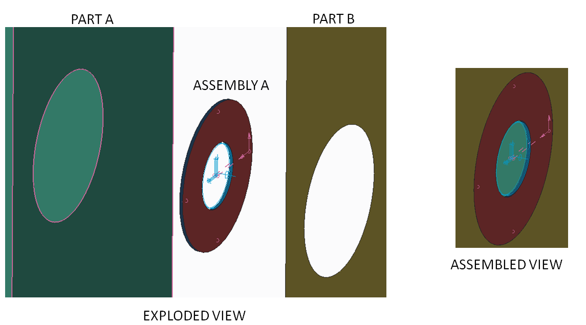
As Steve pointed out, you can't pattern fastener if they are used with the fastener tool. However, if you define a part/assembly that defines the fastener and the area of material that captures the 'radius of influence', then you can pattern this part/assembly. The nice thing about this is that, depending on your model, you can use this method to allow you to quickly change the kinematic nature of the joint (for example, allowing or restricting on-axis rotations). For example:
Assembly A contains two parts: Radius A and Radius B which are connected with a beam element and two weighted-links. Assembly A is placed in an upper-level assembly and used to connect Part A to Part B; in this case, Assembly A represents the fastener. By using a global bonded model definition, the overlapping edges will merge together and result in a beam element connected to a radius of influence on each part. Since Assembly A is an assembly, it can be patterned in Parametric.


Top Tags
