Community Tip - New to the community? Learn how to post a question and get help from PTC and industry experts! X
- Community
- Creo+ and Creo Parametric
- 3D Part & Assembly Design
- 2D cross sections in Drawing file
- Subscribe to RSS Feed
- Mark Topic as New
- Mark Topic as Read
- Float this Topic for Current User
- Bookmark
- Subscribe
- Mute
- Printer Friendly Page
2D cross sections in Drawing file
- Mark as New
- Bookmark
- Subscribe
- Mute
- Subscribe to RSS Feed
- Permalink
- Notify Moderator
2D cross sections in Drawing file
Hello,
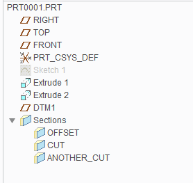
I have a part file in which below three sections [Cut, OFFSET and ANOTHER_CUT] have been created using View->Section as below:

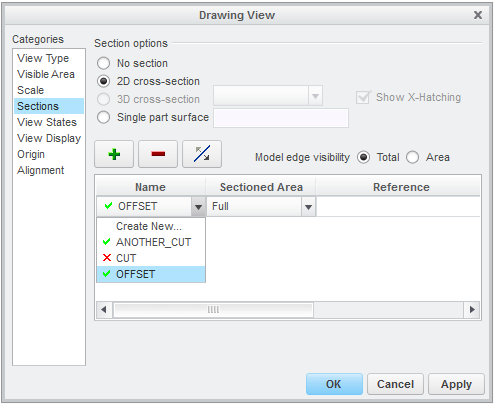
For drawing file of same part, I would like to provide section details in a view. So, I would go to Drawing View manager. Then will select Sections and choose 2-D Cross Section. By clicking on + sign, below will be available:

I would like to know significance of green sign of right and red sign of wrong in front section name. What does these signs indicate?
Thanks and Regards
Ketan
This thread is inactive and closed by the PTC Community Management Team. If you would like to provide a reply and re-open this thread, please notify the moderator and reference the thread. You may also use "Start a topic" button to ask a new question. Please be sure to include what version of the PTC product you are using so another community member knowledgeable about your version may be able to assist.
- Labels:
-
General
- Mark as New
- Bookmark
- Subscribe
- Mute
- Subscribe to RSS Feed
- Permalink
- Notify Moderator
These are both planes/cuts through the view that will work in the view that you are modifying. (i.e. the section plane matches the plane of the view and is not skew to it.)
- Mark as New
- Bookmark
- Subscribe
- Mute
- Subscribe to RSS Feed
- Permalink
- Notify Moderator
Sorry but I am learner of Creo. I am into Creo toolkit. Could you please elaborate it a bit?
Thanks and Regards
Ketan
- Mark as New
- Bookmark
- Subscribe
- Mute
- Subscribe to RSS Feed
- Permalink
- Notify Moderator
If section ABC is in the XY plane, and view 123 is in the XZ plane, section ABC cannot be shown in view 123 because you will not be "looking" in the direction of the sectioned view.
- Mark as New
- Bookmark
- Subscribe
- Mute
- Subscribe to RSS Feed
- Permalink
- Notify Moderator
To try to explain it a different way:
In the model, you have created some sections (cuts) but you have not created any views.
You create views in the drawing. To show a section in the drawing, you must first create a view which is oriented perpendicular to the section cut that you want to show.
In the Sections list, sections which are perpendicular to the selected view are shown with a green tick ("check [mark]" if you speak American). Sections which are not perpendicular have a red cross.


