- Community
- Creo+ and Creo Parametric
- 3D Part & Assembly Design
- Can't break dimensions outside view boundary... ho...
- Subscribe to RSS Feed
- Mark Topic as New
- Mark Topic as Read
- Float this Topic for Current User
- Bookmark
- Subscribe
- Mute
- Printer Friendly Page
Can't break dimensions outside view boundary... how to break manually?
- Mark as New
- Bookmark
- Subscribe
- Mute
- Subscribe to RSS Feed
- Permalink
- Notify Moderator
Can't break dimensions outside view boundary... how to break manually?
Hey guys/gals,
I have had this come up before on rare occasion, but now it is in front of me here in Creo 3 so I wanted to lob it out to you all.
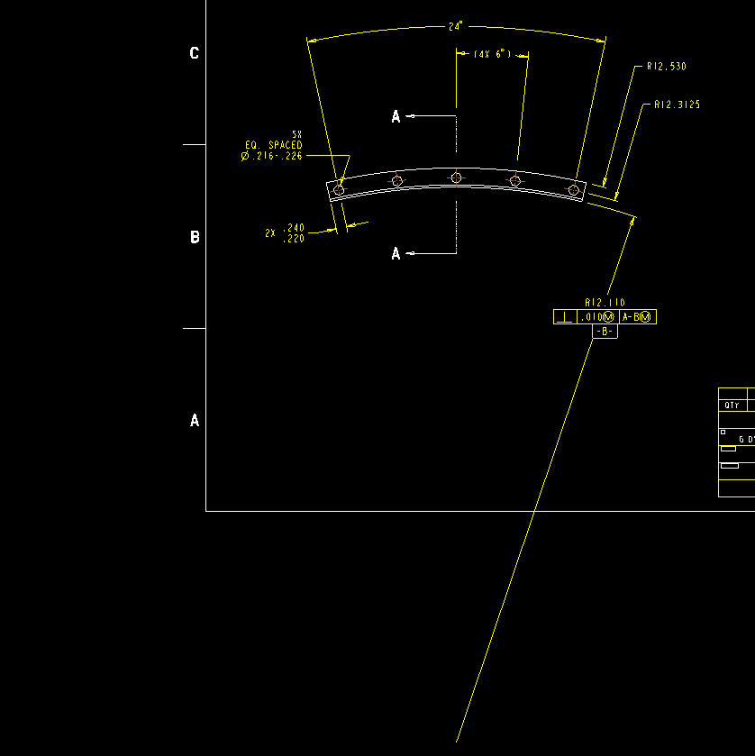
The system is supposedly going to break dimensions for you, or foreshorten them, automatically based on the drawing view boundary and all that. Basically when the dimension falls outside the view box, it should just appear as a double arrow on one side indicating the clip. Well I believe I have all the drawing options on clipping set to yes in the detail config so this should work, however the dims pictures do not seem to observe this setting and I cannot find a way to break them on my own. It's possible I guess that all my previous experience is with linear dims and not radius stuff, but that seems like a poor limitation because round parts are more likely to have an axis well off the page anyways.. but whatever. I did try the help and seriously, the layout and usefulness of that is as badly formatted as this forum. Actually I will give this forum the nod on that because this week I've managed two threads in two tries, with the help, its zero for five.
Does anyone know how to force a break on stuff like this, or what click/pick/setting I am missing in this? The leader clearly leaves the drawing format and after all, we're on pro 34 here. The odds that I am the first one to cross this bridge are beyond lotto.
Please/thanks!!!

This thread is inactive and closed by the PTC Community Management Team. If you would like to provide a reply and re-open this thread, please notify the moderator and reference the thread. You may also use "Start a topic" button to ask a new question. Please be sure to include what version of the PTC product you are using so another community member knowledgeable about your version may be able to assist.
Solved! Go to Solution.
- Labels:
-
2D Drawing
Accepted Solutions
- Mark as New
- Bookmark
- Subscribe
- Mute
- Subscribe to RSS Feed
- Permalink
- Notify Moderator
There is a Z-radius option in the annotation dropdown under the dimension.
That is how you manage very large radii on drawings. However, it is not bug free as I have recently reported an issue still present in Creo 3.
good luck.
Creo Drawing....Cleanup Dimension Issues for diametrical dimensions
- Mark as New
- Bookmark
- Subscribe
- Mute
- Subscribe to RSS Feed
- Permalink
- Notify Moderator
What are you showing in the picture is a radius dimension. The automatic dimension break works for linear and diameter dimensions.
For radius you need to use "Flip Arrow".
- Mark as New
- Bookmark
- Subscribe
- Mute
- Subscribe to RSS Feed
- Permalink
- Notify Moderator
Yes sir, I agree there are several flip options available, but none will let me break the dimension, only convert it to what you see. There are two other radii called out there, two were flipped into leaders, the third was left as shown from center to illustrate this point. As I said, maybe I'm used to linear dims, but it sure seems plausible that a way exists to show an off screen axis without the leader streaking out of view like that.
I don't know if the ASME would agree or not, but personally I don't like putting datum letters on a dim whether its acceptable or not. I would prefer to show an axis with a B on it, and some squiggle line or broken whatever showing my dimension going between. Regardless of my preference though, I would still like to break this thing if its possible.
Thanks for the reply.
- Mark as New
- Bookmark
- Subscribe
- Mute
- Subscribe to RSS Feed
- Permalink
- Notify Moderator
Just to clarify since I used the term break, yes I can use 'break' to cut a piece of the leader out, but that wasn't what I meant as my question.
As an also to your reply, diameter dims act the same way as far as I can see. In fact, they have even less options for flipping so I'm not seeing how to improve my stance that way. The leader layout for them is actually a bit worse but I wouldn't expect this function in a diameter for reasons that are way outside this thread so... anyways, if anyone knows some Jedi level stuff here, post away.

- Mark as New
- Bookmark
- Subscribe
- Mute
- Subscribe to RSS Feed
- Permalink
- Notify Moderator
There is a Z-radius option in the annotation dropdown under the dimension.
That is how you manage very large radii on drawings. However, it is not bug free as I have recently reported an issue still present in Creo 3.
good luck.
Creo Drawing....Cleanup Dimension Issues for diametrical dimensions
- Mark as New
- Bookmark
- Subscribe
- Mute
- Subscribe to RSS Feed
- Permalink
- Notify Moderator
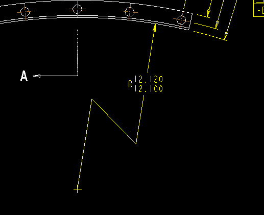
Well, your reply is worth a gold star even though its a good news bad news deal. First the good news, you are correct. The ability to make this type of simple Z-radius dimension is super easy and is just about what I needed. I even noticed you can snap the fake axis inline with the off screen axis to that the dim is on center, nice touch there, that alignment really helps pawn off the dim. Personally I have never even seen this or used it, and due to the enhanced nature of Creo and how organized all the picks are again, there is no chance in hell I would have ever found that pick without you, so thanks...

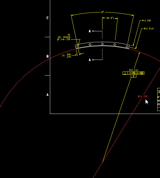
The bad news is the system doesn't allow you to gtol a fake dimension so, close but no cigar for me:

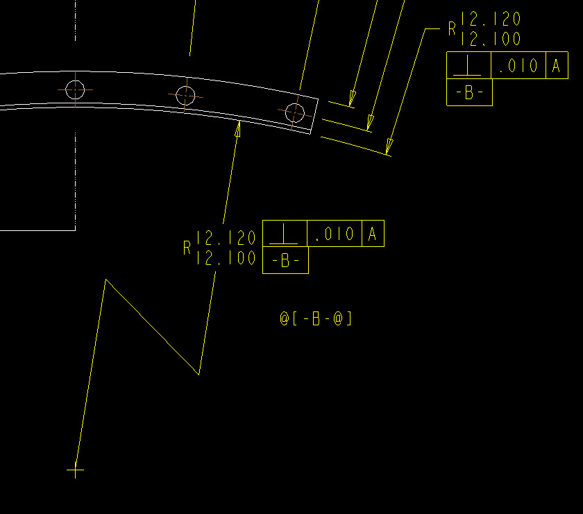
I suppose I could agree that a gtol should never be hitched to a drawing dim, then again, it's drawing mode, I can tell any lie I want here. Well not with the computers help, I guess I have to hack my own work to get something close, lets see how that looks...

Well, I guess it's pretty close. I'm sure the ISO police are logging my IP right now but honestly this would be close enough for me. Other than the fact that I can't tuck the notes in where they belong and make the leaders behave with my trickery, this is a semi-decent work around as long as nobody moves the view or some other boundary deal dooshes me. Then again, why do I need a work around for this... this blows... who authored such a lame limit like this? Could it be this ability has been enhanced for my sake and I just can't tell that I am really saving clicks and working faster? Did this work in pro 17???
Anyways, guess I'll ponder that along side with the other improvement I tripped over... anyone notice what that is? Hint included above...
- Mark as New
- Bookmark
- Subscribe
- Mute
- Subscribe to RSS Feed
- Permalink
- Notify Moderator
Some of that data can be brought forward to other places with its feature ID. I am not an expert at this because I do whatever it takes to make the drawing correct where Creo doesn't accommodate what any good drafter will do to make a ASME qualified document. Never let the tool determine compromise to your good works. Creo detailing is far from complete or efficient. They promised to fix it in Creo 3.0 but they actually made it worse.
- Mark as New
- Bookmark
- Subscribe
- Mute
- Subscribe to RSS Feed
- Permalink
- Notify Moderator
I have a drawing where I 'broke' the main view. There is a radius vertex is in the left side of the broken view and the radius is in the right side of the view. The radius dimension will not foreshorten to line the arrow up on the actual radius, however ends at location off the part on the right. The horizontal dimensions did foreshorten correctly.
?? Creo 2, M100
Kathy
- Mark as New
- Bookmark
- Subscribe
- Mute
- Subscribe to RSS Feed
- Permalink
- Notify Moderator
Hi,
Could you post a picture?
- Mark as New
- Bookmark
- Subscribe
- Mute
- Subscribe to RSS Feed
- Permalink
- Notify Moderator
I am not able to for this particular drawing. I'll try to draw a similar case on my other Creo seat.


