Community Tip - Did you get an answer that solved your problem? Please mark it as an Accepted Solution so others with the same problem can find the answer easily. X
- Community
- Creo+ and Creo Parametric
- 3D Part & Assembly Design
- Creating a UDF where one of the included features ...
- Subscribe to RSS Feed
- Mark Topic as New
- Mark Topic as Read
- Float this Topic for Current User
- Bookmark
- Subscribe
- Mute
- Printer Friendly Page
Creating a UDF where one of the included features requires multiple references
- Mark as New
- Bookmark
- Subscribe
- Mute
- Subscribe to RSS Feed
- Permalink
- Notify Moderator
Creating a UDF where one of the included features requires multiple references
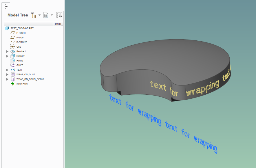
I need to create a UDF for my user group that will create engraved text on the outer diameter of a flange. Also the text needs to be able to rotate around the circumference of the flange a full 360 degrees. This is because there are sometimes other features located on the flange outer diameter that need to be avoided.
So I created the text using the feature list below and this has the ability to be rotated around 360 degrees.
My issue occurs when I create the UDF. When it comes time to select the references for the Offset feature I can only pick one reference (in this case a surface) for the collector in the UDF prompt window. But when creating the Offset feature I am able to select both halves (surfaces) of the outer diameter in order to make the full rotation work. So when placing the newly created UDF in an existing part it works up until you try to rotate the features past 180 degrees then the features start losing references. Obviously this isn't acceptable because I can't have users recreating features for something that was supposed to save them time.
Does anyone have a suggestion for a different approach to create this text or a work around for the UDF creation? Has anyone run into this issue with UDF creation and a different feature?
Also the text does need to be fairly accurate as the CNC Programmers attached to my group will be using these models.
Thanks in advance for the help.
Solved! Go to Solution.
- Labels:
-
General
Accepted Solutions
- Mark as New
- Bookmark
- Subscribe
- Mute
- Subscribe to RSS Feed
- Permalink
- Notify Moderator
Hi,
to avoid problems with cylindrical geometry splitted into two pieces, you have to add additional reference geometry (surface) which will rotate simultaneously with text. See attached model saved in CR3 M120.
MH
Martin Hanák
- Mark as New
- Bookmark
- Subscribe
- Mute
- Subscribe to RSS Feed
- Permalink
- Notify Moderator
Well, I'm not sure how you made that extruded text work; what is the hidden "PROJECTED_TEXT" feature? Can you share your model?
There is a nice discussion about wrapped text here: How to Extrude Wrapped Text
Maybe using their techniques you will be able to generate a UDF that doesn't require surface sets... Also, I notice in Creo 3.0 (maybe it was there before), you can wrap sketches around the "solid geom"; perhaps this is the way to build the UDF such that you don't have to have the multi-surface sets?

Finally, a question: why not just leave the wrapped curve as the "engraving" ? Do you truly need this to be 3D? CNC guys should be able to trace the wrapped curves to program their toolpaths...
- Mark as New
- Bookmark
- Subscribe
- Mute
- Subscribe to RSS Feed
- Permalink
- Notify Moderator
The hidden sketch "PROJECTED_TEXT" is the projection of the wrapped text back onto the sketch plane. I used it with the Offset tool to cut the outside diameter of the part. It may be a bit over kill but it makes the 3D look better also with the Offset tool you are able to make the side walls of the text perpendicular to the surface not the sketch.
I attached the model I created in order to make the UDF, it is a Creo 3.0 version part.
Thanks for the link to the other discussion I will read through that and see if I can use anything from there. The programmers where the ones who requested the feature be 3D, but I will give them some parts with just the sketches and see how it works out.
- Mark as New
- Bookmark
- Subscribe
- Mute
- Subscribe to RSS Feed
- Permalink
- Notify Moderator
Hi,
to avoid problems with cylindrical geometry splitted into two pieces, you have to add additional reference geometry (surface) which will rotate simultaneously with text. See attached model saved in CR3 M120.
MH
Martin Hanák
- Mark as New
- Bookmark
- Subscribe
- Mute
- Subscribe to RSS Feed
- Permalink
- Notify Moderator
Thank you Martin this method works well and removes the need for multiple references when creating the UDF.


