Community Tip - You can Bookmark boards, posts or articles that you'd like to access again easily! X
- Community
- Creo+ and Creo Parametric
- 3D Part & Assembly Design
- Creo 2.0 drawing dimension format
- Subscribe to RSS Feed
- Mark Topic as New
- Mark Topic as Read
- Float this Topic for Current User
- Bookmark
- Subscribe
- Mute
- Printer Friendly Page
Creo 2.0 drawing dimension format
- Mark as New
- Bookmark
- Subscribe
- Mute
- Subscribe to RSS Feed
- Permalink
- Notify Moderator
Creo 2.0 drawing dimension format
Hi all
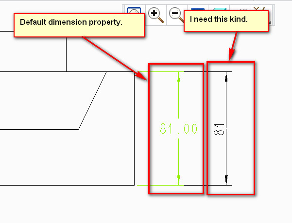
When I create dimensions in drawing, the dimension format is NOT what I want. Thought I can change the dimensions properties but I have too many dimensions to edit. Is there anyway like change config.pro file to achieve the following intention?
1. the zeros behind points don't shown
2. the text orientation is 'Parallel to and above leader'
Please below image.
Thanks
Sylar
This thread is inactive and closed by the PTC Community Management Team. If you would like to provide a reply and re-open this thread, please notify the moderator and reference the thread. You may also use "Start a topic" button to ask a new question. Please be sure to include what version of the PTC product you are using so another community member knowledgeable about your version may be able to assist.
Solved! Go to Solution.
- Labels:
-
2D Drawing
Accepted Solutions
- Mark as New
- Bookmark
- Subscribe
- Mute
- Subscribe to RSS Feed
- Permalink
- Notify Moderator
Sorry, I had to go look this up...
There are a lot of controls for settign specific ISO dimensions in the detail.dtl file.
Here are a few of the basics you are asking about....
- Mark as New
- Bookmark
- Subscribe
- Mute
- Subscribe to RSS Feed
- Permalink
- Notify Moderator
if you change from ASME to ISO, you should get the results you are looking for.
- Mark as New
- Bookmark
- Subscribe
- Mute
- Subscribe to RSS Feed
- Permalink
- Notify Moderator
Thanks. But actually I'm sure I'm using ISO template now.
- Mark as New
- Bookmark
- Subscribe
- Mute
- Subscribe to RSS Feed
- Permalink
- Notify Moderator
Sorry, I had to go look this up...
There are a lot of controls for settign specific ISO dimensions in the detail.dtl file.
Here are a few of the basics you are asking about....
- Mark as New
- Bookmark
- Subscribe
- Mute
- Subscribe to RSS Feed
- Permalink
- Notify Moderator
A good starting point may be one of the predefined DTL files in your:
<loadpoint>\Creo 2.0\Common Files\M040\text location.
According tot he help file, there are 3 predefined files that should be self explanitory:
JIS.DTL
ISO.DTL
DIN.DTL
- Mark as New
- Bookmark
- Subscribe
- Mute
- Subscribe to RSS Feed
- Permalink
- Notify Moderator
Hi Antonius,
This is the correct answer. Thank you. But I still have a issue,
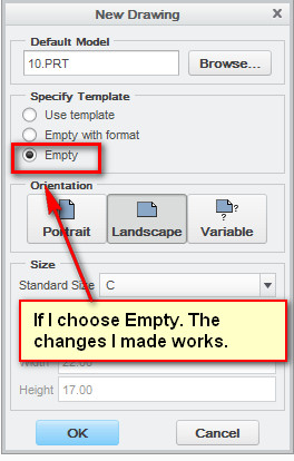
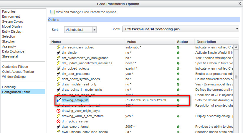
Here is what I've done. I change the value of the two items you mark yellow and save the .dtl file. Then I open Configuration Editor and add drawing_setup_file (The value is the location of .dtl file). I export configurations (save config.pro file). Now when I create a new drawing with empty template, the changes I've made works; but if I create a new drawing with ISO format. I still have the same issue. Do you know why?
- Mark as New
- Bookmark
- Subscribe
- Mute
- Subscribe to RSS Feed
- Permalink
- Notify Moderator
Sylar,
please explain, what is the exact meaning of your sentence ... I create a new drawing with ISO format. If you use template with ISO format, then (I guess) Creo ignores drawing_setup_file option and uses drawing options set inside the template.
Martin Hanak
Martin Hanák
- Mark as New
- Bookmark
- Subscribe
- Mute
- Subscribe to RSS Feed
- Permalink
- Notify Moderator
OK. After I make tha change (edit .dtl file and save it) and export config.pro file (add drawing_setup_file). Then I....pls see below image
>>If I choose Empty. The changes I made works.
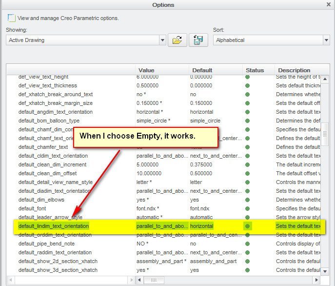
>>If I choose Use template
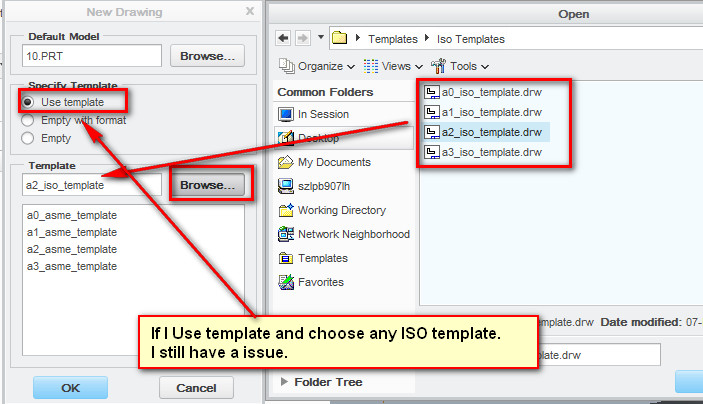
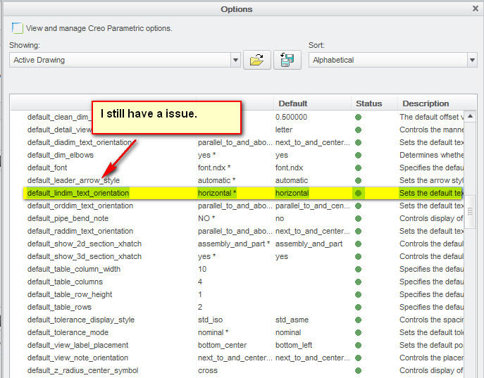
Note: I checked my Configuration Editor in this two circs, drawing_setup_file is working no matter I choose Empty or ISO template.
- Mark as New
- Bookmark
- Subscribe
- Mute
- Subscribe to RSS Feed
- Permalink
- Notify Moderator
Sylar,
I try to explain to you what is going on ![]() .
.
If you create new drawing using Empty option then Creo copies the contents of .dtl file into .drw file. This means that every drawing contains its own set of detail configuration options, which can differ from the current content of .dtl file.
A template is special kind of drawing, therefore it also contains its own set of detail configuration options, which can differ from the current content of .dtl file. You have to open the template, modify its detail configuration options (in Options dialog box you can modify options one by one or you can load current .dtl file) and save it. When you finish this procedure, you will see that your problem is gone.
Martin Hanak
Martin Hanák
- Mark as New
- Bookmark
- Subscribe
- Mute
- Subscribe to RSS Feed
- Permalink
- Notify Moderator
OK. I get your point. Thank you Martin.
- Mark as New
- Bookmark
- Subscribe
- Mute
- Subscribe to RSS Feed
- Permalink
- Notify Moderator
Yes, Sylar. The <detail>.dtl file needs to be read into your session. The default .dtl file is always read into Creo when you boot up the system but if you change it, it is only applicable to the current drawing.
If you use template files, you can read the chosen .dtl file into the template. I find this cumbersome since any change to your template detail.dtl options will have to be done for each sheet size!
The better option I find is to place your <detail>.dtl file in a library location outside the Creo file structure (your own library if you will) and have config.pro open your file when you boot up Creo.
drawing_setup_file C:\...\my_detail_config.dtl
This will always be active no matter what new drawing you open as long as you are -not- using template files. Do not confuse format files with template files. Template files are simply already created drawing files (in this case) that has all the configuration information contained in them.
I always suggest placing library parts outside the Creo file folders. When Creo is updated to a new maintenance release, you stand the chance of loosing valuable configuration files. Ask me how I know ![]()
- Mark as New
- Bookmark
- Subscribe
- Mute
- Subscribe to RSS Feed
- Permalink
- Notify Moderator
- Mark as New
- Bookmark
- Subscribe
- Mute
- Subscribe to RSS Feed
- Permalink
- Notify Moderator
I hope it makes sense to you now. It can be very confusing to new users.
- Mark as New
- Bookmark
- Subscribe
- Mute
- Subscribe to RSS Feed
- Permalink
- Notify Moderator
Right. Thank you! ![]()


