Turn on suggestions
Auto-suggest helps you quickly narrow down your search results by suggesting possible matches as you type.
Showing results for
Turn on suggestions
Auto-suggest helps you quickly narrow down your search results by suggesting possible matches as you type.
Showing results for
Community Tip - Did you know you can set a signature that will be added to all your posts? Set it here! X
- Community
- Creo+ and Creo Parametric
- 3D Part & Assembly Design
- Diameter dimension in sketcher
Options
- Subscribe to RSS Feed
- Mark Topic as New
- Mark Topic as Read
- Float this Topic for Current User
- Bookmark
- Subscribe
- Mute
- Printer Friendly Page
Diameter dimension in sketcher
Oct 23, 2009
06:42 AM
- Mark as New
- Bookmark
- Subscribe
- Mute
- Subscribe to RSS Feed
- Permalink
- Notify Moderator
Oct 23, 2009
06:42 AM
Diameter dimension in sketcher
Is there a way, when sketching a revolved protrusion, to get the default(shown) dimensions to display the diameter of the sketch instead of the radius?
This thread is inactive and closed by the PTC Community Management Team. If you would like to provide a reply and re-open this thread, please notify the moderator and reference the thread. You may also use "Start a topic" button to ask a new question. Please be sure to include what version of the PTC product you are using so another community member knowledgeable about your version may be able to assist.
This thread is inactive and closed by the PTC Community Management Team. If you would like to provide a reply and re-open this thread, please notify the moderator and reference the thread. You may also use "Start a topic" button to ask a new question. Please be sure to include what version of the PTC product you are using so another community member knowledgeable about your version may be able to assist.
Labels:
- Labels:
-
2D Drawing
10 REPLIES 10
Oct 23, 2009
07:48 AM
- Mark as New
- Bookmark
- Subscribe
- Mute
- Subscribe to RSS Feed
- Permalink
- Notify Moderator
Oct 23, 2009
07:48 AM
Shown dimensions show the number as it appears in the sketch. If you dimension your sketch as a diameter--- click sketched line, centerline, and then sketched line again--- you will be able to "show" it as a diameter.
Oct 23, 2009
09:11 AM
- Mark as New
- Bookmark
- Subscribe
- Mute
- Subscribe to RSS Feed
- Permalink
- Notify Moderator
Oct 23, 2009
09:11 AM
What I mean is that when you sketch a revolved protrusion, Pro adds dimensions to the sketch from the centerline to the sketched line. I then must re-dimension the sketch to get the diameter, sketched line, centerline, and then sketched line again. It's this re-dimensioning that need to be avoided.
Oct 23, 2009
09:43 AM
- Mark as New
- Bookmark
- Subscribe
- Mute
- Subscribe to RSS Feed
- Permalink
- Notify Moderator
Oct 23, 2009
09:43 AM
In the sketcher mode I have placed a point on the opposite side of the centerline, constrain it and the edge of the sketch where I wished to pull the diameter, then dimension between the points.
Oct 23, 2009
09:58 AM
- Mark as New
- Bookmark
- Subscribe
- Mute
- Subscribe to RSS Feed
- Permalink
- Notify Moderator
Oct 23, 2009
09:58 AM
Oh, gotcha. Good idea. I just found this. Haven't tried it yet. According to p.141 of WF4 Config Options, add 'sketcher_dim_of_revolve_axis' to config.pro and set to YES. Description: If this option is set all dimensions created by Intent Manager to Axis of Revolution will be diameter dimensions. Give it a shot.
Oct 23, 2009
10:05 AM
- Mark as New
- Bookmark
- Subscribe
- Mute
- Subscribe to RSS Feed
- Permalink
- Notify Moderator
Oct 23, 2009
10:05 AM
Willy, That config option is exactly what I was looking for. Thank you!
Sep 16, 2010
02:54 PM
- Mark as New
- Bookmark
- Subscribe
- Mute
- Subscribe to RSS Feed
- Permalink
- Notify Moderator
Sep 16, 2010
02:54 PM
I will try posting this elsewhere also, but just wondered. Does anyone have a comprehensive list of all config options? Used to have one years ago, but cannot place it now. I am sure there have been additions over the years as well with the new revisions. Thanks !
Sep 16, 2010
05:58 PM
- Mark as New
- Bookmark
- Subscribe
- Mute
- Subscribe to RSS Feed
- Permalink
- Notify Moderator
Sep 16, 2010
05:58 PM
They are on PTC's website.
WF4: http://www.ptc.com/WCMS/files/65779/en/WF4.0_012408_configoptions.pdf
WF5: http://www.ptc.com/WCMS/files/99859/en/WF5M060configoptions.pdf
Not sure if you need specific login access to get to the docs. If you do, let me know and I will see if I can upload them on to PlanetPTC
Jul 31, 2012
01:30 PM
- Mark as New
- Bookmark
- Subscribe
- Mute
- Subscribe to RSS Feed
- Permalink
- Notify Moderator
Jul 31, 2012
01:30 PM
Paul,
I know you posted this back in 2010, but it is just what I was looking for today. The config options for WF4.0.
I was able to get to this without any problems.
Dennis
Jul 31, 2012
04:27 PM
- Mark as New
- Bookmark
- Subscribe
- Mute
- Subscribe to RSS Feed
- Permalink
- Notify Moderator
Jul 31, 2012
04:27 PM
FYI, Creo does this by default now. It seems to re-evaluate the sketch each time you click the "add dimension" button. Once you add a proper centerline(*), it changes your radial intent dimensions to diameters. It does this with angles as well which is a nice improvement from 2000i.
(*) I didn't know we had dedicated centerlines for rotation in Creo (2000i didn't have this). Drove me nuts! ...but I understand why this was needed as you could only use one centerline in 2000i "successfully" in rotations.
Aug 01, 2012
01:34 AM
- Mark as New
- Bookmark
- Subscribe
- Mute
- Subscribe to RSS Feed
- Permalink
- Notify Moderator
Aug 01, 2012
01:34 AM
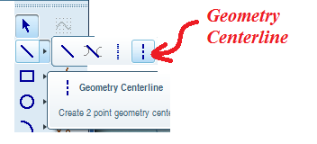
With effect from WF5, PTC has introduced "Geometry Centerline". Sketch the geometry cl first and then sketch the profile for revolve protrusion. The dimensions are then taken as Diameter Diamensions.
I know this is an old post. I am still posting it if it helps somebody.