- Community
- Creo+ and Creo Parametric
- 3D Part & Assembly Design
- Did You Know? Enhanced Datum Feature Symbols Avail...
- Subscribe to RSS Feed
- Mark Topic as New
- Mark Topic as Read
- Float this Topic for Current User
- Bookmark
- Subscribe
- Mute
- Printer Friendly Page
Did You Know? Enhanced Datum Feature Symbols Available in Creo 4.0
- Mark as New
- Bookmark
- Subscribe
- Mute
- Subscribe to RSS Feed
- Permalink
- Notify Moderator
Did You Know? Enhanced Datum Feature Symbols Available in Creo 4.0
If you are deploying model-based definition in your company, you’ll want to download Creo 4.0. We’ve added dozens of enhancements to the software specifically to improve MBD. Among these new capabilities, we've made it easier than ever to create datum feature symbols. Now you can quickly create datum feature symbols anywhere you want, with smart, standards-based placement options that follow the latest GD&T standards. Our expert has the details. Workflows for creating and editing datum feature symbols are more intuitive.
Datum feature symbols can now be created as a stand-alone annotation and do not require a plane or axis in the model.
When you create a datum feature symbol, you can immediately see it in a preview attached to the mouse pointer. You can drag this preview to select the placement location.
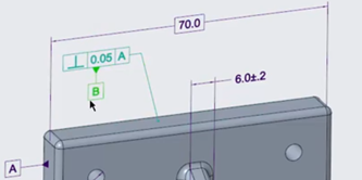
Dragging a datum feature symbol for placement.
There are multiple standards-based placement options which conform to the latest GD&T standards.
Once you have placed the datum feature symbol, the Datum Feature tab appears. Use the options available on this context sensitive tab for editing properties of the datum feature symbol.
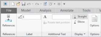
Opening the Datum Feature tab to change properties for the selected datum feature symbol.
When you select the datum feature symbol, the Datum Feature tab opens automatically. When the datum feature symbol is no longer selected, the datum feature tab closes automatically.
You can modify the placement of the datum feature symbol by dragging it.
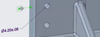
Dragging a datum feature symbol.
If you place a datum feature symbol on a GTOL, you can choose whether it attaches to the GTOL frame or to the leader by choosing the option from the right-click menu.
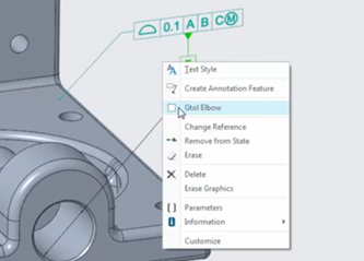
Right-click to open the context menu and select the option to place the datum feature symbol on the GTOL elbow.
Similarly, if you place the datum feature symbol on a diameter dimension, you can choose whether it attaches to the dimension elbow or to the dimension line opposite the dimension text.
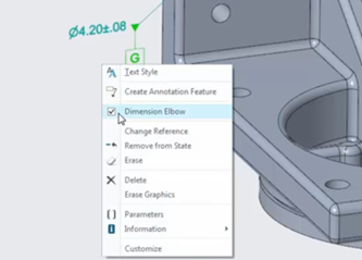
Right-click a datum feature symbol on a diameter dimension to open the context menu and move the symbol opposite the dimension text.
To see a demo of these features, check out the video: https://youtu.be/yULd7Dl5fcA
You can also learn more by reading the PTC Creo Help Center page, More Intuitive Workflows for Creating and Editing Datum Feature Symbols in Model-Based Definition.
If you haven’t already, download the software here and try it yourself. And stay tuned to our “Did You Know” blog series, as we cover more enhancements in PTC Creo 4.0.
- Labels:
-
General
- Mark as New
- Bookmark
- Subscribe
- Mute
- Subscribe to RSS Feed
- Permalink
- Notify Moderator
Why would you need to do that in the model? It would be helpful to know what happened with adding a Datum Plane in the drawing mode. Otherwise it's pretty useless. All this information is going to the drawing in the end.
- Mark as New
- Bookmark
- Subscribe
- Mute
- Subscribe to RSS Feed
- Permalink
- Notify Moderator
The purpose of this instruction is defining a Datum Feature Symbol for Model-Based Definition, otherwise known as MBD. In an MBD environment, the source document is the MBD model with no, partial, or fully annotated features. So in essence, there may be no "drawing" in the end, all the information is captured in the 3D space and not the 2D space.
- Mark as New
- Bookmark
- Subscribe
- Mute
- Subscribe to RSS Feed
- Permalink
- Notify Moderator
The foreseeable outcome is to drive users into either the ASME Y14.100 camp or the MBD camp. I feel like CP4 requires a lot of extra steps in the part, WHICH ARE NOT BEING DEMONSTRATED, to be able to use the new GD&T workflow. Working on a couple of drawings, creating draft GD&T seems much faster. Real or imagined, what matters most is I can attach GD&T symbols to things that aren't pickable in the part (despite the videos that show how easy it is to use MBD).
- Mark as New
- Bookmark
- Subscribe
- Mute
- Subscribe to RSS Feed
- Permalink
- Notify Moderator
In the first paragraph it says "Now you can quickly create datum features symbols anywhere you want,...". CP4 has a problem where if you try to put the datum underneath the dimension, the datum and dimension overlaps. You can't move it down.
Too bad @shoneycutt doesn't realize this is not true.


