

GD&T: Angularity
GD&T Symbol:![]()
Relative to Datum: Yes
MMC or LMC applicable: Yes (Uncommon)
Drawing Callout: 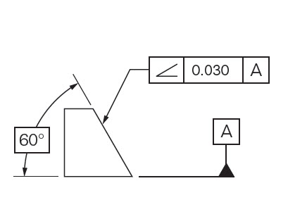
Description:
Angularity is the symbol that describes the specific orientation of one feature to another at a referenced angle. It can reference a 2D line referenced to another 2D element, but more commonly it relates the orientation of one surface plane relative to another datum plane in a 3-Dimensional tolerance zone. The tolerance does not directly control the angle variation and should not be confused with an angular dimension tolerance such as ± 5°. In fact the angle for now becomes a Basic Dimension, since it is controlled by your geometric tolerance. The tolerance indirectly controls the angle by controlling where the surface can lie based on the datum. See the tolerance zone below for more details.
Maximum material condition or axis control can also be called out for angularity although the use in design and fabrication is very uncommon since gauging a hole or pin at an angle is difficult. When angularity is called out on an axis, the tolerance zone now becomes a cylinder around the referenced axis at an angle to the datum. The page on Perpendicularity goes into this type of reference in further detail since it is more common with perpendicularity.
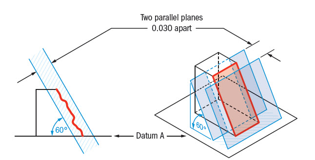
GD&T Tolerance Zone:
Two parallel planes or lines which are oriented at the specified angle in relation to a datum. All points on the referenced surface must fall into this tolerance zone.
Angularity does not directly control the angle of the referenced surface; it controls the envelope (like flatness) that the entire surface can lie.
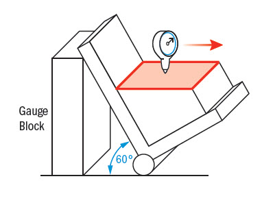
Gauging / Measurement:
Angularity is measured by constraining a part, usually with a sine bar, tilted to the reference angle, so that the reference surface is now parallel to the granite slab. By setting the part at an angle the flatness can now be measured across the now horizontal reference surface. The entire variation must not fall outside the tolerance zone.
Relation to Other GD&T Symbols:
Perpendicularity and Parallelism are actually refined forms of Angularity. Perpendicularity describes angularity at 90° and parallelism describes it at 0°. All of these are profiles of orientation and are used in the exact same way. They also can be used with control of an axis under maximum material condition, although perpendicularity is usually the only one you will ever see with this callout.
Orientation GD&T Symbols are also closely related to flatness when the surfaces are is flat planes. When you call out any of the orientation symbols, flatness is implied (you are measuring a surface variation between two parallel planes = Flatness) However the biggest difference is that orientation callouts are measured with respect to a datum, where flatness is not.
When Used:
Angularity helps control any feature that is at an angle to another datum surface. Anytime you have a critical feature which mates with other part at an angle, angularity can be used to help control the angle and flatness of the mating surfaces. Many stamped parts that have bent features use angularity to ensure that the 3D surface formed by the stamping operation that is formed always is controlled and encased in a tolerance zone.
Example:
If you have a stamped part that had to hook into another part at an angle of 30 degrees, you would want to call out angularity on the “bent” feature to ensure that it is always at its proper orientation. If you did not use angularity you would have to both tighten the angle tolerance of the part and the thickness tolerance of the referenced surface.
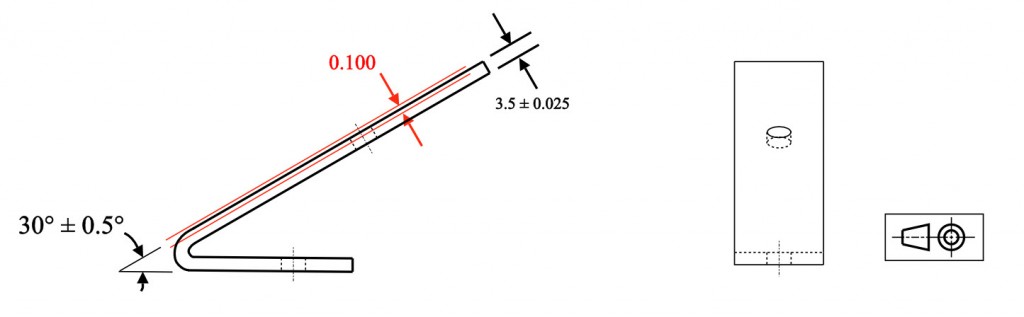
Angularity example 1: Tightening the angle and/or the thickness are required if angularity is not called out.
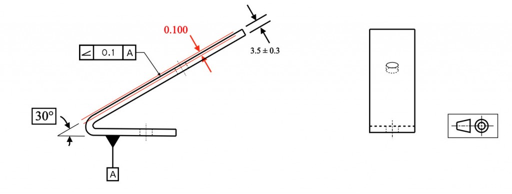
Angularity example 2: A simple call to angularity now ensures that the stamped surface now has both proper angle and flatness. The angle must be a basic dimension, but now allows your part thickness to open up more.
Remember – You are not controlling the angle with angularity – you are controlling the surface to fall within the specified dimensional tolerance in millimeters!
Final Notes to Remember:
Datum Relationship:
Since all of the orientation symbols (Angularity, Perpendicularity, and Parallelism) are referenced to a datum – essentially the tolerance is not measuring a specific surface or feature on its own. You are measuring the relationship of one feature or surface with respect to another feature. If one feature is out – both surfaces could be incorrect.
Maximum Material Condition:
Maximum material condition can also be used in a similar method of perpendicularity. Although MMC is usually for pins or holes which need to be perpendicular to a reference surface, so it is not commonly used on angularity. See Perpendicularity for more details about Gauging and Calling out MMC on an orientation symbol.
Dimensional Angularity:
As stated before: 2-Dimensional references can also be used with angularity to ensure that an angle is met around a round or complex feature. If you wanted to specify the angle of a cone for example, the angularity would apply to each line element along that cone referenced to the bottom of the cone.
This thread is inactive and closed by the PTC Community Management Team. If you would like to provide a reply and re-open this thread, please notify the moderator and reference the thread. You may also use "Start a topic" button to ask a new question. Please be sure to include what version of the PTC product you are using so another community member knowledgeable about your version may be able to assist.