Community Tip - Did you know you can set a signature that will be added to all your posts? Set it here! X
- Community
- Creo+ and Creo Parametric
- 3D Part & Assembly Design
- Helicoil representation in 3D model
- Subscribe to RSS Feed
- Mark Topic as New
- Mark Topic as Read
- Float this Topic for Current User
- Bookmark
- Subscribe
- Mute
- Printer Friendly Page
Helicoil representation in 3D model
- Mark as New
- Bookmark
- Subscribe
- Mute
- Subscribe to RSS Feed
- Permalink
- Notify Moderator
Helicoil representation in 3D model
All,
What do you think is the proper way to show a helicoil drilled and tapped hole in a 3D model? I have not used these in a bit. But I recall showing a drill diameter for the tap only. This to me could be somewhat misleading? I guess I am geared towards paperless designs. I'd like to show the finished tap? I don't know? The finished tap as I understand is not a standard tap size? I think I just read that SolidWorks does have the ability to add those tap sizes via its hole functionality. I do add a model of the heli-coil itself in the sub-assy that follows. Of course it's an interference fit. What are your thoughts on this? I am curious what you all think is an acceptable enough method.
Thanks,
WayneF
- Labels:
-
General
- Mark as New
- Bookmark
- Subscribe
- Mute
- Subscribe to RSS Feed
- Permalink
- Notify Moderator
We have custom hole files and we add in solid models for the Helicoils. We use the models more to drive BOMs than anything else though.
- Mark as New
- Bookmark
- Subscribe
- Mute
- Subscribe to RSS Feed
- Permalink
- Notify Moderator
Interesting. So I am correct that the holes need to be a special condition? Are these holes shown as tapped?
- Mark as New
- Bookmark
- Subscribe
- Mute
- Subscribe to RSS Feed
- Permalink
- Notify Moderator
A 2-step process.
In the part file, show the holes drilled and tapped for the heli-coil insert, Using a custom hole file is the best way to handle that information.
Your final file is the assembly with the heli-coils inserted. This part goes into your next higher assemblies.
We did the same process for parts that had weld studs attached. The blank part file and the assembly with the weld studs.
- Mark as New
- Bookmark
- Subscribe
- Mute
- Subscribe to RSS Feed
- Permalink
- Notify Moderator
I see I am in the right neighborhood of thought here. That's good. I agree with what your saying Ben. I have never used custom holes before. The information would have to be obtained for them. Correct? I would imagine both the minor diameter and the tap diameter would be some odd values?
- Mark as New
- Bookmark
- Subscribe
- Mute
- Subscribe to RSS Feed
- Permalink
- Notify Moderator
If by odd you mean not a standard tap then yes. They are a little bigger. Our holes do not show the 3D geometry of the tap, they are just slightly larger holes. There are quite a few threads in here for custom hole files. Unfortunately they can be a little confusing.
- Mark as New
- Bookmark
- Subscribe
- Mute
- Subscribe to RSS Feed
- Permalink
- Notify Moderator
Yes odd in non standard size and that they are not available in the standard hole list.
Interesting that you say slightly larger hole. I looked up the tap for a 1/4-20 I am using.
Hopefully the above works as a link.
It says Drill bit "H" which is .266. This is in fact larger than 1/4" thread. Should it not be smaller tho?
- Mark as New
- Bookmark
- Subscribe
- Mute
- Subscribe to RSS Feed
- Permalink
- Notify Moderator
No, this tap is used to cut threads for the hole the insert goes into, 1/4-20 referes to the fastener thread. If you want to see values for the hole diameter for the insert look at NASM33537 and the V, V1, and V2 values listed.
- Mark as New
- Bookmark
- Subscribe
- Mute
- Subscribe to RSS Feed
- Permalink
- Notify Moderator
If you're talking the Heli-Coil brand or type inserts (made out of diamond-section wire), they use a larger major diameter (use the one they specify - their custom tap), but have the same exact pitch of the thread you specify. Keenserts are solid inserts, and from what I remember use a larger standard tap (and pitch) than the thread you want.
For modeling purposes, I'd make it an assembly, an model the hole at the minor dia, with a cosmetic thread at the major dia of whatever tap is needed. Then model the inserts as simple hollow cylinders with the major and minor diameters. Done. simple, and your graphics card and processor will thank you, especially in large assemblies. For some reason, the assemblies I'm working on actually has the helical wire of the Heli-Coils modeled....Ugh!
- Mark as New
- Bookmark
- Subscribe
- Mute
- Subscribe to RSS Feed
- Permalink
- Notify Moderator
Similar to what the other guys are saying.
We have a custom hole table containing the parameters from the manufacturer (ours are metric) so the cosmetic thread is shown in the base part. Then we have a family table of wire thread inserts which are a cylinder with a cosmetic thread. As detailed by Frank this is less of a burden on regen times and the items can be shown in the bom.
- Mark as New
- Bookmark
- Subscribe
- Mute
- Subscribe to RSS Feed
- Permalink
- Notify Moderator
I am ok with using either a plain round helicoil or the fancy one you can download from McMaster. I don't have many.
My real question is what to put as tap in the part that receives the helicoil. I can show a thru hole, followed by a cosmetic thread. What would be the values of the 2 diameters?
I am using currently 4-40 & and 1/4-20 helicoils.
Does anyone have a chart?
- Mark as New
- Bookmark
- Subscribe
- Mute
- Subscribe to RSS Feed
- Permalink
- Notify Moderator
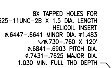
I don't use them but I know of an application here that uses them regularly. I looked two up and this is what we did on those drawings...2 different styles.
The first specifies all the dimensions. The second, we add the taps as a BOM item (qty 0 so they don't buy it for every part)


- Mark as New
- Bookmark
- Subscribe
- Mute
- Subscribe to RSS Feed
- Permalink
- Notify Moderator
As Kevin mentioned you should just specify install per NASM33537. NASM33537 has the information for drill sizes, depths and tolerances. It also has information for how far below the surface the Helicoil should be installed.
- Mark as New
- Bookmark
- Subscribe
- Mute
- Subscribe to RSS Feed
- Permalink
- Notify Moderator
I will see what I can get from that spec. Regardless of how I call them out. My main question remains as to how they should be modeled with the intent to clearly have them represent a helicoil ready hole.
- Mark as New
- Bookmark
- Subscribe
- Mute
- Subscribe to RSS Feed
- Permalink
- Notify Moderator
It's no different than any other threaded part / assembly. ASME Y14.6 gives you 3 methods of representing the threads. The "schematic representation" is actually the most difficult one to reproduce in Creo. so you rarely see anyone trying to do it. "Detailed representation" involves helical cuts and protrusions. It looks pretty, but costs a lot in both modeling time and regeneration time. "Simplified representation" is the easiest one to implement. Internal threads are modeled at the minor diameter with a cosmetic thread at the major diameter. External threads are modeled at the major diameter with a cosmetic thread at the minor diameter.
References to custom hole files is mis-direction. Yes, it's a shortcut if you make a lot of drilled and tapped holes, but it's not a requirement. For an infrequently used custom, manually modeling an internal thread as one or more cuts plus the cosmetic thread is also correct. There aren't "hole" files for external threads, so you have to model it manually anyhow. Yes, you could make UDFs for "external holes", but just take the 2 minutes to model the thing manually and be done with it.
- Mark as New
- Bookmark
- Subscribe
- Mute
- Subscribe to RSS Feed
- Permalink
- Notify Moderator
IF NASM (in my day it was simply NAS) is the spec needed. We used "MS" specs a lot. For his threads, he might not need a "mil-spec".
Typically, if I remember, we did not specify the tap, only the finished thread, and specified: "preparation for and installation of threaded inserts shall be in accordance with......". And we also had a BOM and BOM balloon pointing to the insert.
- Mark as New
- Bookmark
- Subscribe
- Mute
- Subscribe to RSS Feed
- Permalink
- Notify Moderator
I agree Frank. We did the same. just said to be done per.....
I guess I just got it in my head yesterday that maybe the model should be shown a certain way. I would think the correct way is the finished tap that is required to prep these holes. I see the tap on Mcmaster....but did not seem like it had the values I was wanting.
- Mark as New
- Bookmark
- Subscribe
- Mute
- Subscribe to RSS Feed
- Permalink
- Notify Moderator
The NASM standard is the superseding standard for MS33537. The latest revision is from 2013.
- Mark as New
- Bookmark
- Subscribe
- Mute
- Subscribe to RSS Feed
- Permalink
- Notify Moderator
Hi Falco,
not sure if your question is already answered. Maybe this will help anyway.
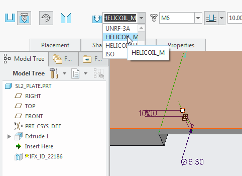
Find attached a PDF for Helicoil inserts. On page 18ff you find all drilling and tapping information.
I also attached our hole chart for inch and metric Helicoils.


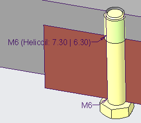
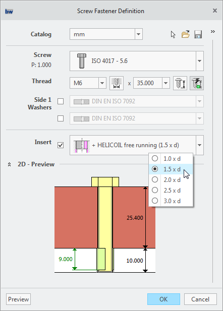
Since Creo 3 you can use the Intelligent Fastener Extension to create fasteners.
It is possible to assemble Inserts with this tool. Use Inserts in IFX

Regards
Oli
- Mark as New
- Bookmark
- Subscribe
- Mute
- Subscribe to RSS Feed
- Permalink
- Notify Moderator
Hi Oliver,
I have a question as to how you constructed the provided hole charts. For example, according to the attached PDF catalog, M6X1 table calls for drill diameter of 6.3mm and the corresponding tap with a max. major diameter of 7.422mm. But your hole chart has 6.3mm tap drill diameter (ok, but with major diameter of 7.300?) I am just curious from where the basic diameter numbers are coming? Is it some kind of a median between specification's max. and min. value?
- Mark as New
- Bookmark
- Subscribe
- Mute
- Subscribe to RSS Feed
- Permalink
- Notify Moderator
Hi Paul,
I created these hole charts long time ago. I cannot remember where I crab the diameter 7.3 from. You are right. It seems like this diameter might not be correct.
I think this diameter depends on a lot of different things.
- The material
- The helicoil tool
- The length of the insert
I recommend to contact the producer of the inserts to get the correct values.
Of course you can modify the hole chart I have uploaded to your needs. This should only be a example on how we use the inserts in our tool.
- Mark as New
- Bookmark
- Subscribe
- Mute
- Subscribe to RSS Feed
- Permalink
- Notify Moderator
Could have come from another standard but ASME B18.29.2M list the minimum major diameter for STI threaded hole data for a M6x1 insert as 7.300.
- Mark as New
- Bookmark
- Subscribe
- Mute
- Subscribe to RSS Feed
- Permalink
- Notify Moderator
Hi Kevin,
this might be possible. I have double checked this.
In the Machinery Handbock the "Min. Major Diam./All Classes" is "7.300".
I think I have taken the value from there.
Thanks.
- Mark as New
- Bookmark
- Subscribe
- Mute
- Subscribe to RSS Feed
- Permalink
- Notify Moderator
OK, makes sense; thank you for the explanation.
- Mark as New
- Bookmark
- Subscribe
- Mute
- Subscribe to RSS Feed
- Permalink
- Notify Moderator
Oliver,
Heavy duty offering. Thanks! Sorry I got pulled away from this stuff.
I am looking thru all your information.
Is IFX on standard loads? I'm wondering if we have the ability to use it.
Wayne
- Mark as New
- Bookmark
- Subscribe
- Mute
- Subscribe to RSS Feed
- Permalink
- Notify Moderator
Hi Wayne,
a free version of IFX is shipped with Creo since version 3.0.
This document shows the difference between the free and the paid version:
The inserts stuff cannot be used with the free version. But if you want I can send you a demo version for IFX so you can test the functionality.
Send your request to oli@buw-soft.de
Find more information about IFX in our group: Intelligent Fastener Extension - IFX
Oli


