Community Tip - Want the oppurtunity to discuss enhancements to PTC products? Join a working group! X
- Community
- Creo+ and Creo Parametric
- 3D Part & Assembly Design
- Hole Tolerance & Decimals on Drawing
- Subscribe to RSS Feed
- Mark Topic as New
- Mark Topic as Read
- Float this Topic for Current User
- Bookmark
- Subscribe
- Mute
- Printer Friendly Page
Hole Tolerance & Decimals on Drawing
- Mark as New
- Bookmark
- Subscribe
- Mute
- Subscribe to RSS Feed
- Permalink
- Notify Moderator
Hole Tolerance & Decimals on Drawing
Hello,
I'm having trouble with hole callouts in my drawings. I'm trying to avoid just making a text note and instead have it linked to actual dimensions for the hole, but PTC is not making it easy.
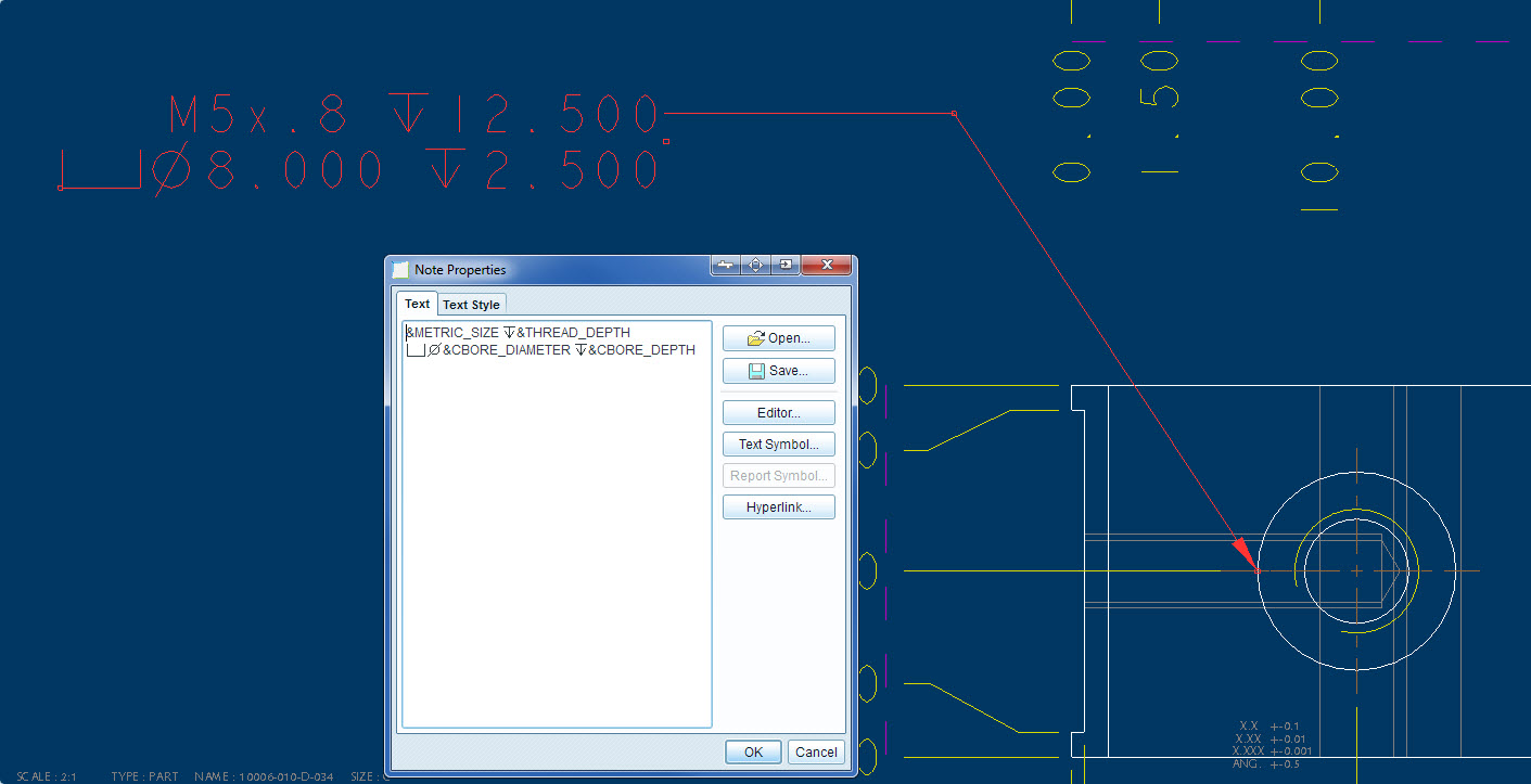
I've created my own note for the hole and the format is fine. My big trouble is getting the right tolerance labels on the hole. I would like there to be plus/minus limits and 2 decimal places, but I only get a note like this:

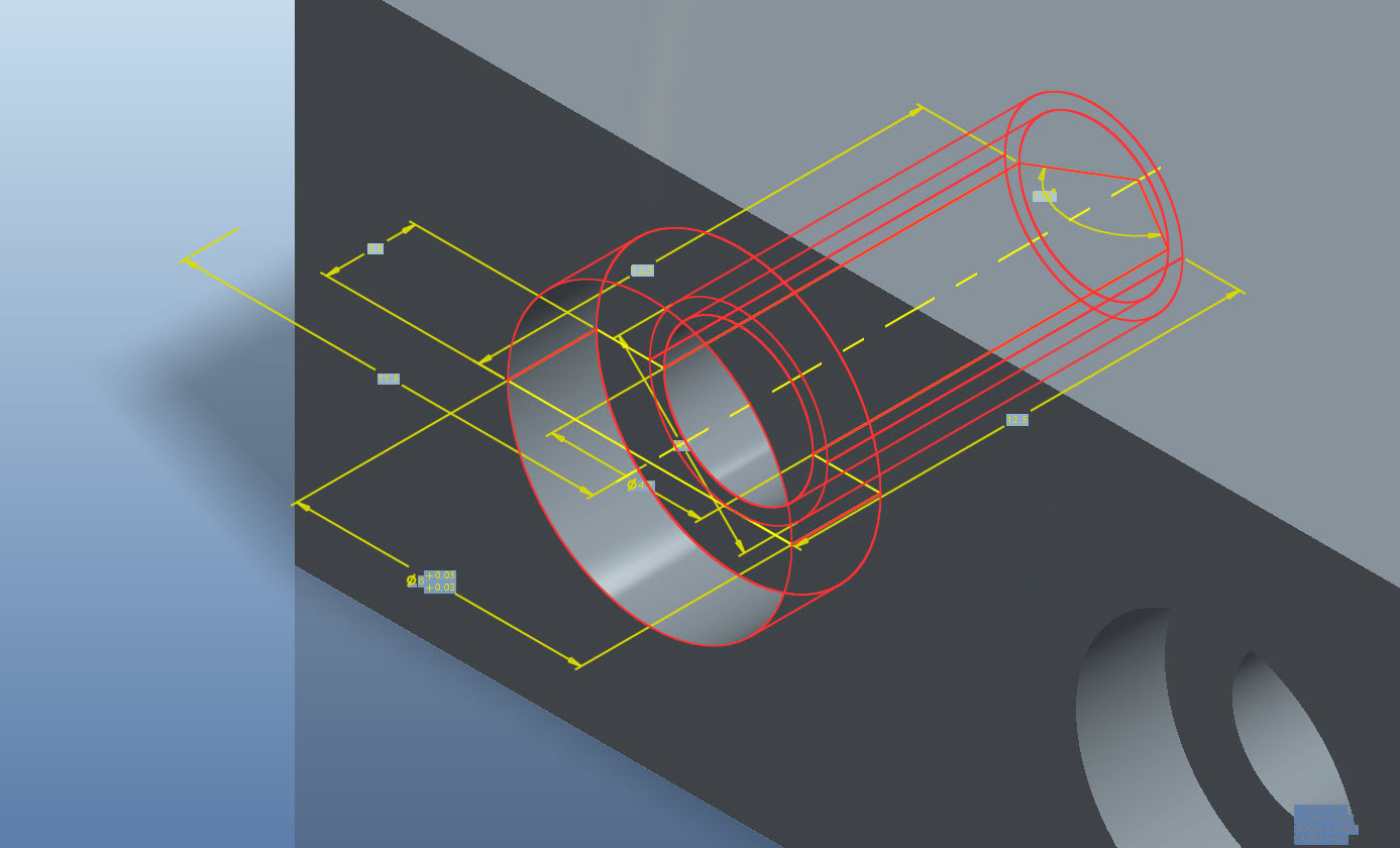
I've tried clicking on everything I know in the drawing. I've even gone to "edit" the hole feature on the part and change the tolerances there as well. You can see my plus minus tolerance on the diameter of the hole below:

Is there some setting in the note that I need to set in order to show the proper X.XX tolerance and the plus/minus limits? I'm creating this note using the "Show Model Annotations" button. Also, I've searched forums and web and haven't found any relevant information.
Any help you can provide would be appreciated. Thanks!
This thread is inactive and closed by the PTC Community Management Team. If you would like to provide a reply and re-open this thread, please notify the moderator and reference the thread. You may also use "Start a topic" button to ask a new question. Please be sure to include what version of the PTC product you are using so another community member knowledgeable about your version may be able to assist.
- Labels:
-
Sheet Metal Design
- Mark as New
- Bookmark
- Subscribe
- Mute
- Subscribe to RSS Feed
- Permalink
- Notify Moderator
This is a tough one, Tyler. You can access the dimension tolerances on an individual basis but formatting them into the hole note may be more challenging.
I fully appreciate your need to do this. With ISO dimensioning practices, I tolerance every single dimension on the drawing. No title block or feature size tolerancing is acceptable in this case for local manufacturing. You have to be specific for precision machine parts. Providing a status for every dimension also forces the engineer to look more closely at what is being specified.
I don't try to use the built-in notes for holes. I typically just edit a drafting dimension (radial dims tend to follow the arc better than notes) and edit this to show the associative dimensions from the model. I can give the c-bore a tolerance and that dimension will show the tolerance in the edited radial dim.
The problem is in the fact that PTC does a lot behind the scenes with the values of the hole definition. That is why the tolerance is being lost, because it is not part of the "transformed" value.
There are several other bugs in the hole system that really get to me like superfluous spaces at inconvenient locations for imperial callouts... UNC - 2B rather than UNC-2B for instance. From a completeness and fit -n- finish standpoint, I find the old methods to be more reliable for all instances.
In general, we all have to figure out how we want to deal with the limitations of the software. There is no -right- way... just what you are willing to do to make it work for you.
- Mark as New
- Bookmark
- Subscribe
- Mute
- Subscribe to RSS Feed
- Permalink
- Notify Moderator
Perhaps these will help:
Tolerances—Parameters associated with tolerance formats. These symbols appear when dimensions are switched from numeric to symbolic.
- tpm#—Tolerance in plus-minus symmetrical format; # is the dimension number.
- tp#—Positive tolerance in plus-minus format; # is the dimension number.
- tm#—Negative tolerance in plus-minus format; # is the dimension number.


