Community Tip - Learn all about the Community Ranking System, a fun gamification element of the PTC Community. X
- Community
- Creo+ and Creo Parametric
- 3D Part & Assembly Design
- How to calculate the Developed length in Pro/Sheet...
- Subscribe to RSS Feed
- Mark Topic as New
- Mark Topic as Read
- Float this Topic for Current User
- Bookmark
- Subscribe
- Mute
- Printer Friendly Page
How to calculate the Developed length in Pro/Sheetmetal?
- Mark as New
- Bookmark
- Subscribe
- Mute
- Subscribe to RSS Feed
- Permalink
- Notify Moderator
How to calculate the Developed length in Pro/Sheetmetal?
Hi All,
Can anyone help me to calculate the developed length in Creo/ProE Sheetmetal.
Thanks in Advance
Amit
This thread is inactive and closed by the PTC Community Management Team. If you would like to provide a reply and re-open this thread, please notify the moderator and reference the thread. You may also use "Start a topic" button to ask a new question. Please be sure to include what version of the PTC product you are using so another community member knowledgeable about your version may be able to assist.
Solved! Go to Solution.
- Labels:
-
Sheet Metal Design
Accepted Solutions
- Mark as New
- Bookmark
- Subscribe
- Mute
- Subscribe to RSS Feed
- Permalink
- Notify Moderator
I see, there are bend allowances based on the material. These are values that you can enter or allow to default based on pre-defined tables.
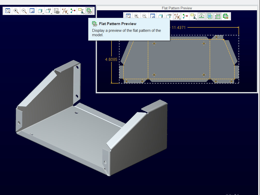
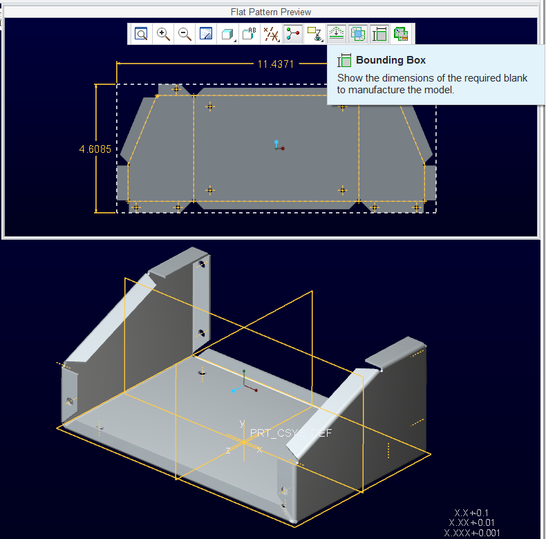
In general, there is stretch and crush going on in the bend. If you overall size is 100x100 and 100x50, then the result will the slightly less that 150. in Creo 2.0, in the flat view pop-out window, you can have the overall size shown by using the button on the graphics toolbar in the pop-out window.


- Mark as New
- Bookmark
- Subscribe
- Mute
- Subscribe to RSS Feed
- Permalink
- Notify Moderator
Can you clarify your question?
- Mark as New
- Bookmark
- Subscribe
- Mute
- Subscribe to RSS Feed
- Permalink
- Notify Moderator
I have a sheet with bend wall. Now after unbend the total length of the sheet should be including the radius of the bend.
E.g. Sheet is of 100X100 and bend wall attached is of 100X50 with radius = thickness.
After unbend what should be the total length.
- Mark as New
- Bookmark
- Subscribe
- Mute
- Subscribe to RSS Feed
- Permalink
- Notify Moderator
I see, there are bend allowances based on the material. These are values that you can enter or allow to default based on pre-defined tables.
In general, there is stretch and crush going on in the bend. If you overall size is 100x100 and 100x50, then the result will the slightly less that 150. in Creo 2.0, in the flat view pop-out window, you can have the overall size shown by using the button on the graphics toolbar in the pop-out window.


- Mark as New
- Bookmark
- Subscribe
- Mute
- Subscribe to RSS Feed
- Permalink
- Notify Moderator
Thanks Antonius,
But where I can find the bend table for refernce.
And can we perform Thick & Thickness Analysis(formabilty Simulation) in Creo Simulate?
- Mark as New
- Bookmark
- Subscribe
- Mute
- Subscribe to RSS Feed
- Permalink
- Notify Moderator
I know very little about simulate. The bend tables are here: ...\Creo 2.0\Common Files\M030\text\bend_tables
Don't ask me how to read them. When I need to know, I use the 60%/40% rule in a section. I wouldn't trust my setting in Creo to provide to a shop. I would have to know exactly what they really use for bend dies. I trust that most use a generic .032" IR brake die whether they're bending aluminum or steel. Thicker gauges, more of course. But for prototyping, I trust the defaults to be within manufacturing tolerances.
- Mark as New
- Bookmark
- Subscribe
- Mute
- Subscribe to RSS Feed
- Permalink
- Notify Moderator
Thanks Antonius,
It is really a great help..
Regards
Amit
- Mark as New
- Bookmark
- Subscribe
- Mute
- Subscribe to RSS Feed
- Permalink
- Notify Moderator
This may be too late but further to the answer from Antonuis, you might find the linked document below interesting reading.
http://www.ciri.org.nz/bendworks/bending.pdf
It shows how to calculate the K-factor using measurements taken from a physical sample before and after bending. You can then use the K-factor in Pro/E to calculate the bend allowance.
There is also a freeware calculator on their website.
- Mark as New
- Bookmark
- Subscribe
- Mute
- Subscribe to RSS Feed
- Permalink
- Notify Moderator
That is an excellent reference, Colin. Thanks!
- Mark as New
- Bookmark
- Subscribe
- Mute
- Subscribe to RSS Feed
- Permalink
- Notify Moderator
That was of great learning reference, Colin..
Thanks


