Community Tip - You can Bookmark boards, posts or articles that you'd like to access again easily! X
- Community
- Creo+ and Creo Parametric
- 3D Part & Assembly Design
- Re: How to simulate a bolted joint with a round ho...
- Subscribe to RSS Feed
- Mark Topic as New
- Mark Topic as Read
- Float this Topic for Current User
- Bookmark
- Subscribe
- Mute
- Printer Friendly Page
How to simulate a bolted joint with a round hole and slot
- Mark as New
- Bookmark
- Subscribe
- Mute
- Subscribe to RSS Feed
- Permalink
- Notify Moderator
How to simulate a bolted joint with a round hole and slot
I have a assembly with two parts that use a round hole and slot for the bolted joint. I cannot use the fasteners tool due to the slot, how do I model the bolted joint?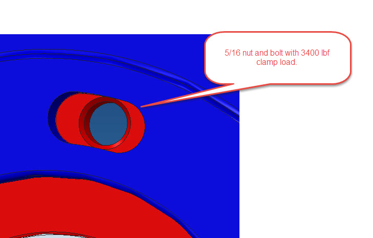
- Labels:
-
Assembly Design
- Mark as New
- Bookmark
- Subscribe
- Mute
- Subscribe to RSS Feed
- Permalink
- Notify Moderator
Have you tried solid models with the new preload constraint now availible in Creo 2 Simulate or newer?
- Mark as New
- Bookmark
- Subscribe
- Mute
- Subscribe to RSS Feed
- Permalink
- Notify Moderator
I am using Creo 2.0, but I am not familar with the solid models and preload you are referring to. Is there a reference doc you can point me to?
- Mark as New
- Bookmark
- Subscribe
- Mute
- Subscribe to RSS Feed
- Permalink
- Notify Moderator
Dan,
Try using a simplified 3d model of the bolt and nut using the following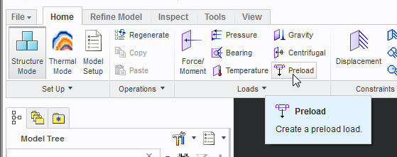
- Mark as New
- Bookmark
- Subscribe
- Mute
- Subscribe to RSS Feed
- Permalink
- Notify Moderator
Don,
Thank you for the help. I have searched PTC university and this site and cannot find a reference to the "preload" function you show above ( all searches reference the fastener tool). I played with the tool and got a loadcase, but I am not sure how the tool actually works. Is there a doc that shows how to define the preload for different cases?
- Mark as New
- Bookmark
- Subscribe
- Mute
- Subscribe to RSS Feed
- Permalink
- Notify Moderator
What do you want to simulate with this setup and are the slots a necessary part of this simulation?
The help files will aid you much better for this topic.
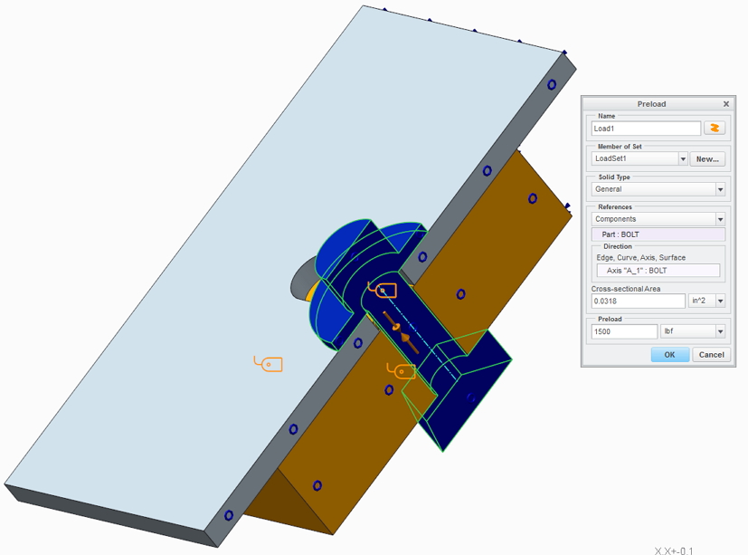
Basically:
- Create a single part that represents a bolt+nut
- Assemble the part to the hole
- Create a "preload" load
- Click on preload
- Change solid type to "general"
- Change reference to "components"
- Select your bolt+nut part
- Select a bolt axis for the direction
- Enter your cross-sectional area
- Enter your desired preload
- Mark as New
- Bookmark
- Subscribe
- Mute
- Subscribe to RSS Feed
- Permalink
- Notify Moderator
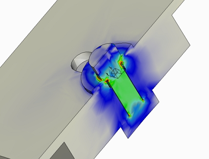
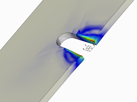
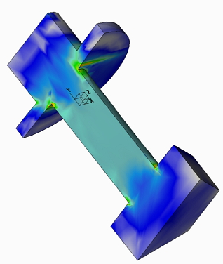
I need to keep the slots,as the part has a rotational load also. I ran a analysis with the bolt per the description above. It ran and showed a stress distribution similar to above. I will mess with it more and try to get a better understanding of how the loads are applied. Thanks for the help!
- Mark as New
- Bookmark
- Subscribe
- Mute
- Subscribe to RSS Feed
- Permalink
- Notify Moderator
Dan,
I personally prefer to use a beam element (point to point) to model the bolt, datum points at the bolt ends, and rigid or weighted links between bolt endpoints and the bolted components. I use a zero coeff. of thermal expansion, and a high coeff. of thermal expansion for the bolts. Prescribe a -1 global temp load, and the beam will contract and thus produce a pre-load. A couple of runs are often needed to tune the temp. (or coeff of thermal exopansion) to get the correct preload.
Unfortunately, this can't be done in a large deformation contact analysis, but it is useful in many situations. I think the "fasteners" etc. work a bit like a "black box" - I don't quite understand what's going on. Using a beam + temp load to create pre-load I have full control, no issues with geometry etc. /Mats Lindqvist
- Mark as New
- Bookmark
- Subscribe
- Mute
- Subscribe to RSS Feed
- Permalink
- Notify Moderator
I have never tried to use the preload feature with a solid bolt that was an unique part (screw + nut), but I've always had screw and nut linked with a bonded region.
I think is the same thing, I don't see why not.
To apply the right preload you have to do like the fastener:
- apply a first preload F1
- put a measure of force on the area of the volume region where you've placed the preload or the thermal load on the bolt
- first analysis
- take note of the measure of force F2
- modify the preload in this manner F1^2/F2
- second analysis
Bye
- Mark as New
- Bookmark
- Subscribe
- Mute
- Subscribe to RSS Feed
- Permalink
- Notify Moderator
Hello,
I tried to simulate a threaded connection with solid bolts and the preload feature, because I want to compare the results to the same model with fasteners instead of solid bolts. The procedure is clear to me in theory. Practiacally the simulation always (except of the one time I succeeded to get measure F2) failed tue to insufficient constraints. I have calculated the new preload value and want to verify in another simulation. But it always failes in the second loop because of insufficient constraints (single pass analysis). A trial with MPA and grade 1 succeeds.
There is a bonded region between bolt and threaded part and a contact between the head of the bolt and the clamped part. All other constraines stayed the same to the model with the fasteners.
I allready inserted a spring to support the clamped part.
I assume there is a convergence problem but have no idea how to solve it.
Creo Simulate is Version 2.0
Many thanks in advance for any support!


