Community Tip - Did you know you can set a signature that will be added to all your posts? Set it here! X
- Community
- Creo+ and Creo Parametric
- 3D Part & Assembly Design
- Re: How to use surface model in a drawing
- Subscribe to RSS Feed
- Mark Topic as New
- Mark Topic as Read
- Float this Topic for Current User
- Bookmark
- Subscribe
- Mute
- Printer Friendly Page
How to use surface model in a drawing
- Mark as New
- Bookmark
- Subscribe
- Mute
- Subscribe to RSS Feed
- Permalink
- Notify Moderator
How to use surface model in a drawing
I imported a IGS surface model that was built in PowerShape. There are many Gaps/Slivers and difficult to fix in IDD and solidify. Since my task is to make a drawing for matching the PowerShape model only, I am trying to use the surface model vs. solid in drawing. Everything looks fine except Edge Display and Line Style. All of surface lines are shown in solid.
Do anyone have experience on surface model in drawing?
How to show hidden line of the surface model in dot or phantom vs. solid in drawing?
Thanks
Solved! Go to Solution.
- Labels:
-
Surfacing
- Tags:
- surface modelling
Accepted Solutions
- Mark as New
- Bookmark
- Subscribe
- Mute
- Subscribe to RSS Feed
- Permalink
- Notify Moderator
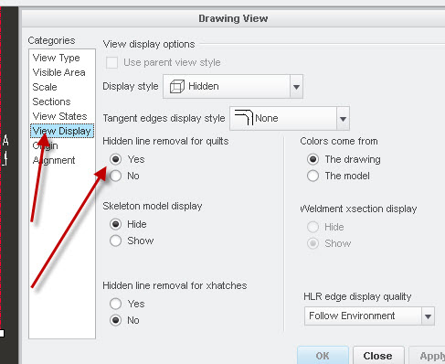
And for hidden lines, in the drawing view properties dialog box, view display, there is a hidden line removal for quilts option.

- Mark as New
- Bookmark
- Subscribe
- Mute
- Subscribe to RSS Feed
- Permalink
- Notify Moderator
And for hidden lines, in the drawing view properties dialog box, view display, there is a hidden line removal for quilts option.

- Mark as New
- Bookmark
- Subscribe
- Mute
- Subscribe to RSS Feed
- Permalink
- Notify Moderator
Thank you a lot!
Is it normal practice to use a surface model in a drawing? or it is wrong way?
- Mark as New
- Bookmark
- Subscribe
- Mute
- Subscribe to RSS Feed
- Permalink
- Notify Moderator
I would say it is not a normal practice to use a surface model in a drawing, but each drawing is created for different needs of communicating design intent especially early concept drawings and not final detail drawings. As you can see by the need to change numerous settings to get the same look you would with a solid model that out of the box Pro/E/Creo is not set up by default that way. Is it wrong? No, there are many different ways to get what you want. Inheriting dumb CAD files in STEP and IGES formats can be a real pain and timely to fix to make a solid, so you must do what you have to do with the given files and time. Keep in mind if the drawing is to manufacture a part or just identify a part or component that is to be purchased
- Mark as New
- Bookmark
- Subscribe
- Mute
- Subscribe to RSS Feed
- Permalink
- Notify Moderator
Thank you very much!


