Community Tip - Want the oppurtunity to discuss enhancements to PTC products? Join a working group! X
- Community
- Creo+ and Creo Parametric
- 3D Part & Assembly Design
- Problem with Manual Transmission
- Subscribe to RSS Feed
- Mark Topic as New
- Mark Topic as Read
- Float this Topic for Current User
- Bookmark
- Subscribe
- Mute
- Printer Friendly Page
Problem with Manual Transmission
- Mark as New
- Bookmark
- Subscribe
- Mute
- Subscribe to RSS Feed
- Permalink
- Notify Moderator
Problem with Manual Transmission
Hello Guys
Few days ago I have started doing my project, I want to design manual transmission. I have found nice video and I based on it. Here is It:
https://www.youtube.com/watch?v=wCu9W9xNwtI
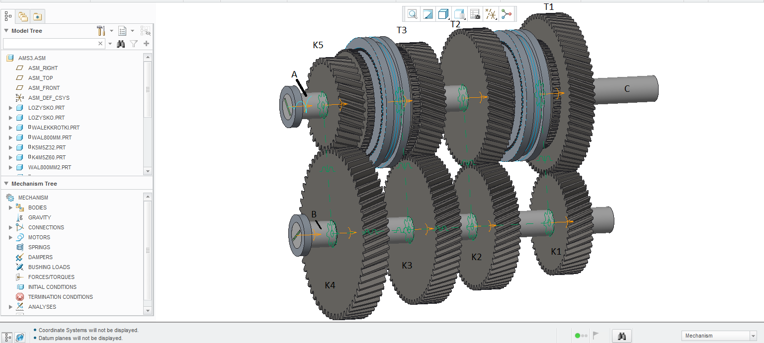
I want to get same result as shown in 5:10. I have drown all components which I need and the next step is to connect all components as assembly. I’m trying to make assembly with neutral gear and this is what I have:

Here I have first question. To make all gears work correctly I used Pin connection to all turning around components(shaft “C” on neutral gear doesn’t turn around). I used Spur Gears to connect K5-K4, K3-T3, K2-T2, K1-T1. But It was not enough, mechanism didn’t work correctly so I used Generic Gear to connect K4-K3, K4-K2, K4-K1. Am I do it all well(I am asking if this is good conception)? So, when I do that the problem occur. Shaft A and B doesn’t rotate with the same speed as gears K5 and K4 have. I created servo motor as shaft A, I give it Velocity profile and put some constant value of velocity. Next I went to Mechanism Analysis and made Kinematic Analysis with my servo motor, then I make a movie form Playback and this is what I got:
Guys I have tried do something to solve this problem but now I’m out of ideas. Can anyone help?
- Labels:
-
Assembly Design


