- Community
- Creo+ and Creo Parametric
- 3D Part & Assembly Design
- Re: Sheetmetal problem: Creo Elements/Pro 5.0
- Subscribe to RSS Feed
- Mark Topic as New
- Mark Topic as Read
- Float this Topic for Current User
- Bookmark
- Subscribe
- Mute
- Printer Friendly Page
Sheetmetal problem: Creo Elements/Pro 5.0
- Mark as New
- Bookmark
- Subscribe
- Mute
- Subscribe to RSS Feed
- Permalink
- Notify Moderator
Sheetmetal problem: Creo Elements/Pro 5.0


Hi all,
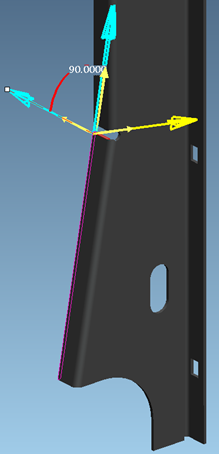
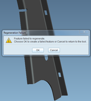
I have a problem (red marked area) with a sheetmetal part, see the pictures above. The part has been generated in Creo Elements/pro 5.0. As you can see the software can generate a flat model of this part even though there is a penetration! Since it's not feasible in the production I tried to add a cut. After the cut was added a flat model couldn be generated.
I can't understand the reason why the software is able to process a defective geometry at all, but not a proper geometry that is feasible and can be easily manufactured.
Has someone an idea how to resolve this problem?
Thank you very much!
Michael
- Labels:
-
Sheet Metal Design
- Tags:
- sheetmetal_challenge
- Mark as New
- Bookmark
- Subscribe
- Mute
- Subscribe to RSS Feed
- Permalink
- Notify Moderator
If the cut does not result in perpendicular edges then the modeler won't be able to flatten it.
- Mark as New
- Bookmark
- Subscribe
- Mute
- Subscribe to RSS Feed
- Permalink
- Notify Moderator
For clarification, perpendicular as compared to the edge that will be flattened?
- Mark as New
- Bookmark
- Subscribe
- Mute
- Subscribe to RSS Feed
- Permalink
- Notify Moderator
I mean if you work along the cut edges of the part; it won't work if to make the part the sheet metal would need to be sheared at an angle to the flattened sheet face. I don't know if there is a reason besides error checking that this is prevented, but it seems to be, so no tapers to the nominal thickness.
- Mark as New
- Bookmark
- Subscribe
- Mute
- Subscribe to RSS Feed
- Permalink
- Notify Moderator


Hi,
Thanks for a quick response! As you can see the cut is perpendicular to the edges even though it can't generate a flat model. Another issue is (see original question) why it can deal very well with a defected geometry including a penetration.
Regards,
Michael
- Mark as New
- Bookmark
- Subscribe
- Mute
- Subscribe to RSS Feed
- Permalink
- Notify Moderator
Can you upload the model? How to Attach a File to a Discussion Reply
From you images, I don't see anything that would prevent a flat from being created.
As far as why it is able to create a flat when it overlaps with other flat geometry, it's always been able to do that, it's one of those odd things that it shouldn't do but it does.
- Mark as New
- Bookmark
- Subscribe
- Mute
- Subscribe to RSS Feed
- Permalink
- Notify Moderator
- Mark as New
- Bookmark
- Subscribe
- Mute
- Subscribe to RSS Feed
- Permalink
- Notify Moderator
I can't find the problem of why it won't unbend after you cut in the flat, but I'm completely out of practice on sheet metal work these days.
My suggestion would be to re-do the model to avoid the flat pattern overlap completely. Many, many times I know I have come up with my parts and decided to re-model the part since the model I used to design with was not a very robust model due to the iterations made during the design.
- Mark as New
- Bookmark
- Subscribe
- Mute
- Subscribe to RSS Feed
- Permalink
- Notify Moderator
It needs to be perpendicular in the thickness direction. The most likely place for this to not be correct is where the round notch intersects the fillet/bend.
Also, It's best if the notch is such that, when flattened, the two flanges don't intersect. Right now it looks like the flanges would run into each other when flattened.


