Community Tip - Stay updated on what is happening on the PTC Community by subscribing to PTC Community Announcements. X
- Community
- Creo+ and Creo Parametric
- 3D Part & Assembly Design
- Stop Case 1/Stop Case 2 Chamfer
- Subscribe to RSS Feed
- Mark Topic as New
- Mark Topic as Read
- Float this Topic for Current User
- Bookmark
- Subscribe
- Mute
- Printer Friendly Page
Stop Case 1/Stop Case 2 Chamfer
- Mark as New
- Bookmark
- Subscribe
- Mute
- Subscribe to RSS Feed
- Permalink
- Notify Moderator
Stop Case 1/Stop Case 2 Chamfer

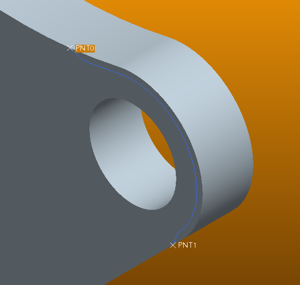
I'm trying to igure out a way to create this chamfer without doing a sweep. Please see image.
I need a chamfer on the edge, between the two points. I can do stop at reference, but can't seem to select more than one point on which to stop. As you see, I need it between two points.
I can't seem to find the option for stop cases, either.
I'm new to Creo Elements/ Pro E 5.0, but have seven years modeling experience. Thanks in advance for your assistance!
This thread is inactive and closed by the PTC Community Management Team. If you would like to provide a reply and re-open this thread, please notify the moderator and reference the thread. You may also use "Start a topic" button to ask a new question. Please be sure to include what version of the PTC product you are using so another community member knowledgeable about your version may be able to assist.
Solved! Go to Solution.
- Labels:
-
General
Accepted Solutions
- Mark as New
- Bookmark
- Subscribe
- Mute
- Subscribe to RSS Feed
- Permalink
- Notify Moderator
Hi Kris
Chamfer at stop reference has certain limitations
But you can select Plane instead of point for defining Stop Reference( As I have tried in the following image)
This will give you some useful results
I would not say this is a very good solution; But I want to just share some of the Creo/Pro-Engineers Features.
I hope you will find it interesting
Regards
K.Mahanta
- Mark as New
- Bookmark
- Subscribe
- Mute
- Subscribe to RSS Feed
- Permalink
- Notify Moderator
I haven't seen the chamfer command do that before, but if a round would serve your purpose you can use that blue curve on your part as a guide for the round. See "thru curve" option within round command.
But, a sweep would be the better choice. However, don't use "Sweep" use "Variable Section Sweep". It will give you what you want without the cascading menus. Variable Section Sweep doesn't mean that you have to vary the section. It just an option.
That's a good looking background color. What are the RGB values?
- Mark as New
- Bookmark
- Subscribe
- Mute
- Subscribe to RSS Feed
- Permalink
- Notify Moderator
Unfortunately I need a chanfer, not a fillet. Thanks for the suggestion. ![]()
That's a blended background. Top color is 248, 153, 6 and the bottom is 84, 46, 2.
- Mark as New
- Bookmark
- Subscribe
- Mute
- Subscribe to RSS Feed
- Permalink
- Notify Moderator
Really, use the Variable Section Sweep to achieve the chamfer. I believe it to be what the majority of the users here would do. Well, they would use one of the two sweep commands I mentioned earlier, that is.
- Mark as New
- Bookmark
- Subscribe
- Mute
- Subscribe to RSS Feed
- Permalink
- Notify Moderator
Hi
Do you want to chamfer with in certain limits?
Check the following
This may help you
There might be some more options
(I rarely use these options)
Regards
K.Mahanta
- Mark as New
- Bookmark
- Subscribe
- Mute
- Subscribe to RSS Feed
- Permalink
- Notify Moderator
Hi
Also check this
- Mark as New
- Bookmark
- Subscribe
- Mute
- Subscribe to RSS Feed
- Permalink
- Notify Moderator
I haven't had a chance to try this, but as soon as I do I'll report back. Thank you!
- Mark as New
- Bookmark
- Subscribe
- Mute
- Subscribe to RSS Feed
- Permalink
- Notify Moderator
Nice write-up kshetrabasi. However, I think Kris will need to do a sweep anyways because if he's using some kind of milling cutter, there will be a conical "turnout" at the ends where the tool stops or the tool path interpolates out of the part.
Also, to Kevin: Yes, you can use a VSS with a constant section, but I'd really advise using a simple swept feature whenever possible as VSS's make the file size larger and the file more complicated that it needs to be. Now, sometimes a trajectory that SHOULD be good will not work for a sweep, and then you're FORCED to use a VSS or swept blend, but for something as simple as this, I'd certainly use a blend.
Another caveat: Avoid using conics in a sketched section if possible too. They're powerful shapes, but can cause issues downstream.
- Mark as New
- Bookmark
- Subscribe
- Mute
- Subscribe to RSS Feed
- Permalink
- Notify Moderator
In this case, Kris happens to be a "she". ![]()
- Mark as New
- Bookmark
- Subscribe
- Mute
- Subscribe to RSS Feed
- Permalink
- Notify Moderator
![]()
![]() Its an easy mistake to make, Frank.
Its an easy mistake to make, Frank.
Frank, thanks for the manufacturing perspective and the tip about the burden the VSS causes on the system. I'll keep it in mind.
Kris, thanks for the background colors, I'm using them. Its a strong color mix, but for now I like it.
- Mark as New
- Bookmark
- Subscribe
- Mute
- Subscribe to RSS Feed
- Permalink
- Notify Moderator
Hah! Oops, sorry Kris. I didn't look at your profile to see. ![]()
Anytime Kevin. ![]() I have a manufacturing background, so I tend to be very conscious of that stuff. I didn't see any parting lines or draft on the part, and there would have to be on the ends of the chamfer even if it did come to a dead stop like that, so I figured from the geometry it was being machined.
I have a manufacturing background, so I tend to be very conscious of that stuff. I didn't see any parting lines or draft on the part, and there would have to be on the ends of the chamfer even if it did come to a dead stop like that, so I figured from the geometry it was being machined.
I don't know why sometimes a simple sweep considers a trajectory "invalid", but that's an enhancement PTC should make. I've had to do a bunch of VSS's or Swept Blends before simply because I couldn't use a trajectory I'd created.
- Mark as New
- Bookmark
- Subscribe
- Mute
- Subscribe to RSS Feed
- Permalink
- Notify Moderator
Nice work Kshetrabasi!
- Mark as New
- Bookmark
- Subscribe
- Mute
- Subscribe to RSS Feed
- Permalink
- Notify Moderator
For the end geometry you could create a boundary blend or a filled sketch if you still want to work without sweeps.
- Mark as New
- Bookmark
- Subscribe
- Mute
- Subscribe to RSS Feed
- Permalink
- Notify Moderator
When I try this, the box where you select the stops is greyed out. I also can't add any transitions. Did I miss something?
Thanks
- Mark as New
- Bookmark
- Subscribe
- Mute
- Subscribe to RSS Feed
- Permalink
- Notify Moderator
Hi
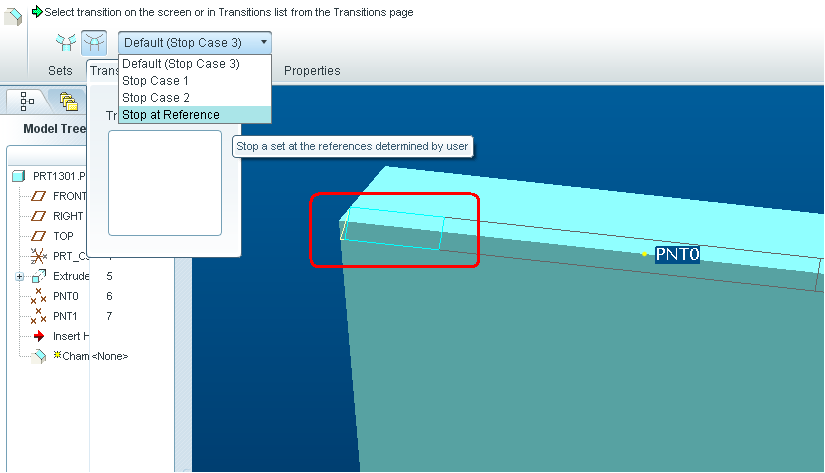
When you see no options; you have to select end piece (as highlighted in Red Box in the image)
This will enable the options
Regards
K.Mahanta

- Mark as New
- Bookmark
- Subscribe
- Mute
- Subscribe to RSS Feed
- Permalink
- Notify Moderator
What is that "end piece" that you have highlighted?
I tried your example using the same geometry of two straight edges connected by a radius, and I was able to pick the datum points as stop refs. But, the feature failed when I clicked the green check.
Can you make this same type of chamfer on a cylinder? I was not able to do so.
Thanks,
Kevin
- Mark as New
- Bookmark
- Subscribe
- Mute
- Subscribe to RSS Feed
- Permalink
- Notify Moderator
I don't think you can do that on a cylinder end with the chamfer feature there are no transition ends. You can create the geometry with other features. Might be helpful if you can show what error you are getting.
- Mark as New
- Bookmark
- Subscribe
- Mute
- Subscribe to RSS Feed
- Permalink
- Notify Moderator
I'm experimenting with the procedure that Kshetrabasi has shown. I don't think it can be done on a cylinder either, but I also didn't think you could set up stop points for a chamfer--I was wrong about that, maybe. I say maybe because I was not able to create what he did.
The trick is to have transitions that can be defined and with the cylinder no transitions were available.
I'm just curious about what's possible. If it were my model I would still use the variable section sweep.
-Kevin
- Mark as New
- Bookmark
- Subscribe
- Mute
- Subscribe to RSS Feed
- Permalink
- Notify Moderator
Hi
I hope this will clarify some of your doubts
http://communities.ptc.com/videos/2730
Regards
K.Mahanta
- Mark as New
- Bookmark
- Subscribe
- Mute
- Subscribe to RSS Feed
- Permalink
- Notify Moderator
Thanks for the vid, I got it to work.
- Mark as New
- Bookmark
- Subscribe
- Mute
- Subscribe to RSS Feed
- Permalink
- Notify Moderator
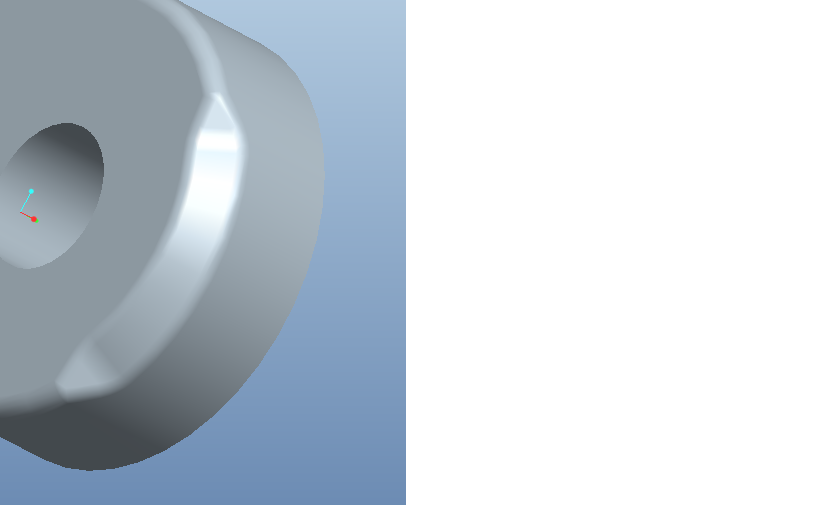
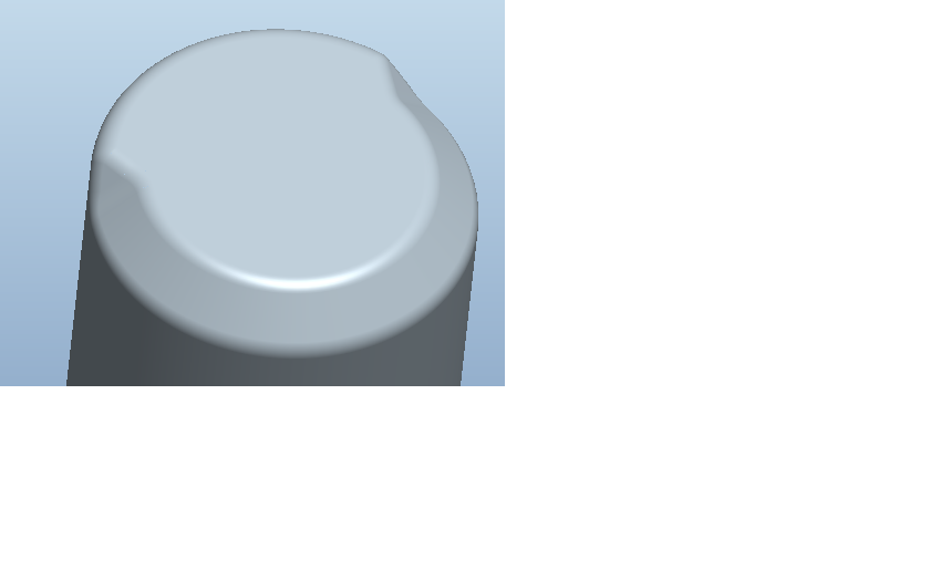
Here are some images of what I ended up with without using a VSS.


- Mark as New
- Bookmark
- Subscribe
- Mute
- Subscribe to RSS Feed
- Permalink
- Notify Moderator
Looks good. What tools did you use?
- Mark as New
- Bookmark
- Subscribe
- Mute
- Subscribe to RSS Feed
- Permalink
- Notify Moderator
For the first image I used the chamfer with the stop at reference, boundary blends to create the end geometry (you need to extend the boundary blend surface edges where it meets the two surfaces otherwise you might get intersection errors), and solidify to remove the remaining material.
The second image was created with a revolve and specifying stop points for the two sides of the feature, boundary blends for the end geometry, and solidify to remove the remaining material.
You could also create the end geometry by creating a filled sketch but you need to setup datums for the sketch construction.
- Mark as New
- Bookmark
- Subscribe
- Mute
- Subscribe to RSS Feed
- Permalink
- Notify Moderator
Sounds like the simplest solution os to use a swept cut. No need for a VSS on simple geometry and with a simple trajectory like this. And, it appears a swept cut would give you the proper cutter geometry anyway, so why do anything else? Why the hesitation to use a sweep Kris?
- Mark as New
- Bookmark
- Subscribe
- Mute
- Subscribe to RSS Feed
- Permalink
- Notify Moderator
Because it technically is a chamfer. But I will not be able to get the end geometry using the chamfer command - the "blend" ouf of the chamfer on both ends. I have it as a sweep now, but wanted to know how to do the chamfer. I'm learning Pro and couldn't figure it out, so I asked. ![]()
- Mark as New
- Bookmark
- Subscribe
- Mute
- Subscribe to RSS Feed
- Permalink
- Notify Moderator
Don't get hung up on whether things are actually "chamfers" or "rounds". You can always rename the feature and call it what you want. The key thing is getting the geometry right. THAT'S the only thing that actually matters. And in this case, it isn't really a "chamfer" anyways, it's the result of an interpolated toolpath (sweep) using a chamfer cutting tool, is it not? ![]()
There are usually a couple of different ways to do things in Pro/E, the simplest that actually gets the geometry needed is always the best option.
Good luck!
- Mark as New
- Bookmark
- Subscribe
- Mute
- Subscribe to RSS Feed
- Permalink
- Notify Moderator
Tomatoe, tomato..LOL
Thanks Frank.
- Mark as New
- Bookmark
- Subscribe
- Mute
- Subscribe to RSS Feed
- Permalink
- Notify Moderator
Hi Kris
Chamfer at stop reference has certain limitations
But you can select Plane instead of point for defining Stop Reference( As I have tried in the following image)
This will give you some useful results
I would not say this is a very good solution; But I want to just share some of the Creo/Pro-Engineers Features.
I hope you will find it interesting
Regards
K.Mahanta
- Mark as New
- Bookmark
- Subscribe
- Mute
- Subscribe to RSS Feed
- Permalink
- Notify Moderator
kshetrabasi,
I actually needed to use this again today. I took a look at your video and was able to do it on the second try. Thanks so much! It's great to learn new things!
- Mark as New
- Bookmark
- Subscribe
- Mute
- Subscribe to RSS Feed
- Permalink
- Notify Moderator
Ok Kris, here's one for you: I had a case where I wanted to stop a round on both sides of a part (mirror image) at a face. I went thru all the different options of the stop cases, realized I'd have to do it as surfaces and do a bunch of monkeying around before I could use a solidify/cut to remove the material, and decided to just sweep a surface, put a fill surface cap on it at the vertical surface, and then remove the material with the solidify/cut. It ended up being 7 features total as opposed to being 2 IF I could have gotten the rounds to work as solid rounds, but I couldn't and stopped wasting time trying. Sometimes, it's best to just use what works and not Get hung up on whether it's "technically" a "round" feature or not. Get it done, and move on. As I've always said, a good Pro/E user knows the commands. A great user knows the Pro/WORKAROUNDS (and is Pro/FICIENT in the use of the Pro/FANITY module)! ![]()


