Community Tip - You can Bookmark boards, posts or articles that you'd like to access again easily! X
- Community
- Creo+ and Creo Parametric
- 3D Part & Assembly Design
- Subtract one solid from another
- Subscribe to RSS Feed
- Mark Topic as New
- Mark Topic as Read
- Float this Topic for Current User
- Bookmark
- Subscribe
- Mute
- Printer Friendly Page
Subtract one solid from another
- Mark as New
- Bookmark
- Subscribe
- Mute
- Subscribe to RSS Feed
- Permalink
- Notify Moderator
Subtract one solid from another
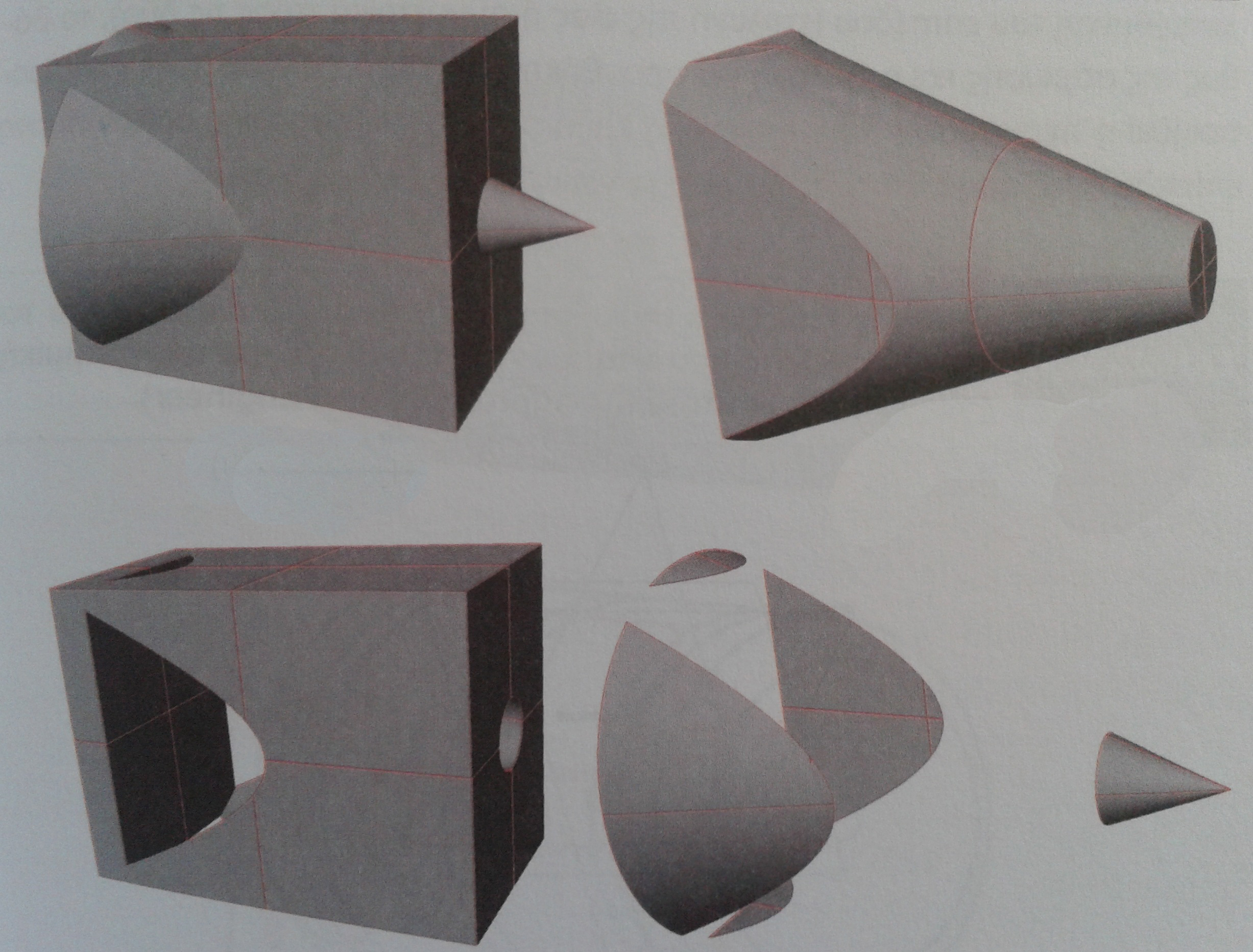
Hello everyone! I m new in Creo 3.0 and need some help. I want to create a part. In that part I need to subtract one solid from another, let's say a cone from a cube. Is this possible on the same part file? Attached, a photo from a book to exactly show you what I mean.

This thread is inactive and closed by the PTC Community Management Team. If you would like to provide a reply and re-open this thread, please notify the moderator and reference the thread. You may also use "Start a topic" button to ask a new question. Please be sure to include what version of the PTC product you are using so another community member knowledgeable about your version may be able to assist.
Solved! Go to Solution.
Accepted Solutions
- Mark as New
- Bookmark
- Subscribe
- Mute
- Subscribe to RSS Feed
- Permalink
- Notify Moderator
I think you're obliged to use surfaces. Here boolean operations in one part file as already told.
- Mark as New
- Bookmark
- Subscribe
- Mute
- Subscribe to RSS Feed
- Permalink
- Notify Moderator
- Mark as New
- Bookmark
- Subscribe
- Mute
- Subscribe to RSS Feed
- Permalink
- Notify Moderator
Thank you very much dema! Though, if there is a way to do that in a single part and not in assembly, it would be ideal. Any ideas?
- Mark as New
- Bookmark
- Subscribe
- Mute
- Subscribe to RSS Feed
- Permalink
- Notify Moderator
A part cannot have multiple solids in Creo. However, you can create the two surface bodies and merge them together to generate the options you've shown above.
If you have two part files, you can also copy the geometry from one to the other using the Copy Geometry feature to copy the surfaces of one part into the other. That does require the Advanced Assembly Extension, however.
- Mark as New
- Bookmark
- Subscribe
- Mute
- Subscribe to RSS Feed
- Permalink
- Notify Moderator
With the advanced assembly extention, you can use the Merge/Inheritance feature to add or subtract a part from your model.
We use it here for molded parts. A base part is created and several coreout models are also created to subtract material. A new part is made, using Merge/Inheritance, by adding the base part and removing the coreouts needed.
There is always more to learn in Creo.
- Mark as New
- Bookmark
- Subscribe
- Mute
- Subscribe to RSS Feed
- Permalink
- Notify Moderator
I think you're obliged to use surfaces. Here boolean operations in one part file as already told.
- Mark as New
- Bookmark
- Subscribe
- Mute
- Subscribe to RSS Feed
- Permalink
- Notify Moderator
I think this is what I need Mauro. Thanx a lot! If you could give me some more detailed instuctions on how to do that, it would be perfect.
- Mark as New
- Bookmark
- Subscribe
- Mute
- Subscribe to RSS Feed
- Permalink
- Notify Moderator
File I attached is made in Creo3. Can you open and explore it? If you need the same file in another version of Creo, no problem!
Make a video can take a little more...
- Mark as New
- Bookmark
- Subscribe
- Mute
- Subscribe to RSS Feed
- Permalink
- Notify Moderator
No problem Mauro, I just made it. thanks a lot! ![]()
- Mark as New
- Bookmark
- Subscribe
- Mute
- Subscribe to RSS Feed
- Permalink
- Notify Moderator
You actually CAN have two distinct, separate solids in a single part, just not connected, or if they would partially or completely occupy the same space, not at the same time (suppress one or the other).
For what you are doing, if you want 2 different parts, you can create the surfaces in the generic, and then make family table instances containing the merges/intersects needed to get what you want (suppressing one or the other), all driven from within the same part with no external references needed. Also, as simple as the geometry looks, you could use datum curves, and simply drive solids from them with a cut feature. It'd be simpler than using surfaces.


