Community Tip - Learn all about the Community Ranking System, a fun gamification element of the PTC Community. X
- Community
- Creo+ and Creo Parametric
- 3D Part & Assembly Design
- Surface modeling
- Subscribe to RSS Feed
- Mark Topic as New
- Mark Topic as Read
- Float this Topic for Current User
- Bookmark
- Subscribe
- Mute
- Printer Friendly Page
Surface modeling
- Mark as New
- Bookmark
- Subscribe
- Mute
- Subscribe to RSS Feed
- Permalink
- Notify Moderator
Surface modeling
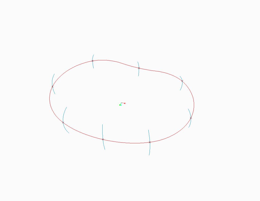
I have some problem constructing a surface out of an irregular trajectory. As shown in below image, the trajectory is the red-coloured line, the outer profile was constructed with multiple sketch profiles combined at certain datum point. I wanted to create a surface that follow the trajectory as well as all the blue-lined sketch enclosed as the wall.
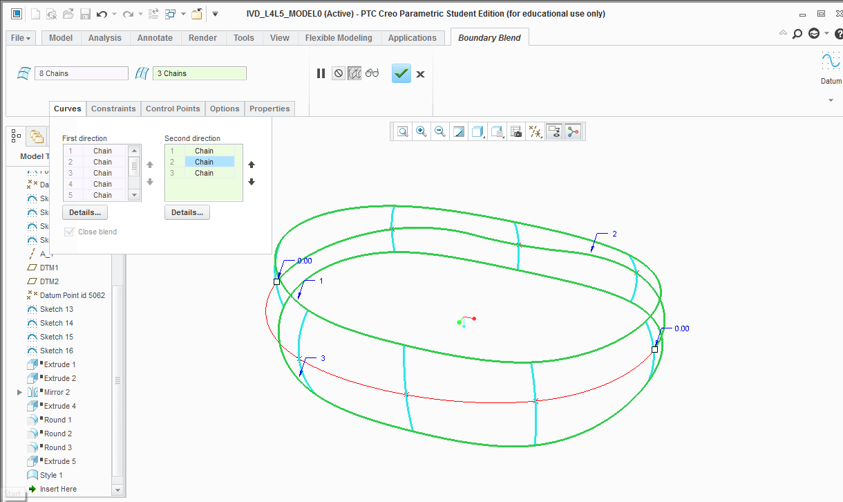
Initially, I intended to use boundary blend command, with all the blue-lined sketch selected as 'First Direction' + close blend enabled, and the red-sketch as the 'Second Direction', but seems like it requires another sketch to be selected. When I construct another curve line of at the end of each wall using surface-curve command and tried again using the 'boundary blend' feature, the following happens (see image below) -- only partial selection of the red-coloured-line -- which doesn't allow the surface to be constructed.
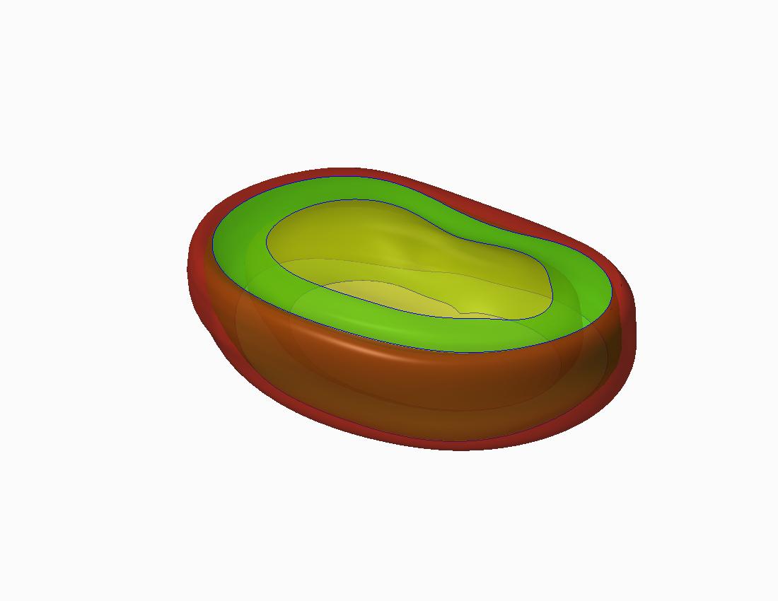
For your reference on how I intend the profile to be, the following are some image of the previous model that I manage to construct. Thanks in advance for your help and suggestion.

This thread is inactive and closed by the PTC Community Management Team. If you would like to provide a reply and re-open this thread, please notify the moderator and reference the thread. You may also use "Start a topic" button to ask a new question. Please be sure to include what version of the PTC product you are using so another community member knowledgeable about your version may be able to assist.
- Labels:
-
General
- Mark as New
- Bookmark
- Subscribe
- Mute
- Subscribe to RSS Feed
- Permalink
- Notify Moderator
I can think of many ways to construct this, however I'll address the things in your post.
You can select the entire red curve by picking the initial segment (as you have done) and then holding "shift" to build a chain of the other segments. I would then add the bottom curve as well, through the lower end points of your cross curves, and build with 3 curves in one direction and 8 in the other.
- Mark as New
- Bookmark
- Subscribe
- Mute
- Subscribe to RSS Feed
- Permalink
- Notify Moderator
...or, as I like to do, highlight that curve and go into the "Details" tab below, which allows you to select by rules, intent chain, loop, etc.
- Mark as New
- Bookmark
- Subscribe
- Mute
- Subscribe to RSS Feed
- Permalink
- Notify Moderator
didn't work. Can't seem to select the curve as complete loop etc.
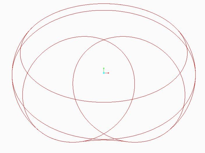
Here's the preliminary sketch feature that make out the outer line.
- Mark as New
- Bookmark
- Subscribe
- Mute
- Subscribe to RSS Feed
- Permalink
- Notify Moderator
Hi..i think that's what I did in the first place. the final blend became very distorted as the 'red-coloured'curve' were sketched with multiple shapes being put together, while the end curve were based only on the end point of the wall (blue-coloured) line.
- Mark as New
- Bookmark
- Subscribe
- Mute
- Subscribe to RSS Feed
- Permalink
- Notify Moderator
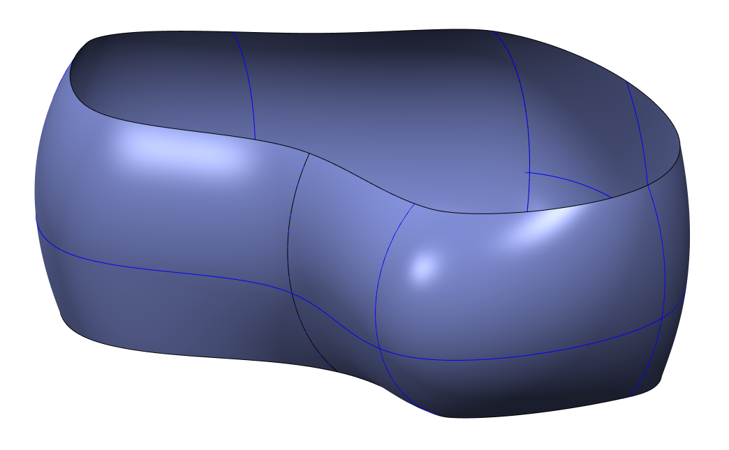
I recently modeled a part similar to this where I needed several different sketched sections swept through a trajectory. You might consider using a swept blend feature for this. You should be able to use your existing sketches.
Here's something I whipped up using a swept blend.
- Mark as New
- Bookmark
- Subscribe
- Mute
- Subscribe to RSS Feed
- Permalink
- Notify Moderator
Hi... almost got the feature that I wanted. Just wondering if the above figure was constructed out of multiple swept blend function? How about the trajectory? Seems like my trajectory is split up that some region (wall/blue-coloured-line) are not covered by the trajectory...


