Community Tip - Learn all about the Community Ranking System, a fun gamification element of the PTC Community. X
- Community
- Creo+ and Creo Parametric
- 3D Part & Assembly Design
- User created views
- Subscribe to RSS Feed
- Mark Topic as New
- Mark Topic as Read
- Float this Topic for Current User
- Bookmark
- Subscribe
- Mute
- Printer Friendly Page
User created views
- Mark as New
- Bookmark
- Subscribe
- Mute
- Subscribe to RSS Feed
- Permalink
- Notify Moderator
User created views
How do I create a section view in my model so I can bring it into my drawing? When I bring the section view into my drawing it is at one of the standard planes. I need my view to be normal to the screen. I need my view to show up in the view selection box.
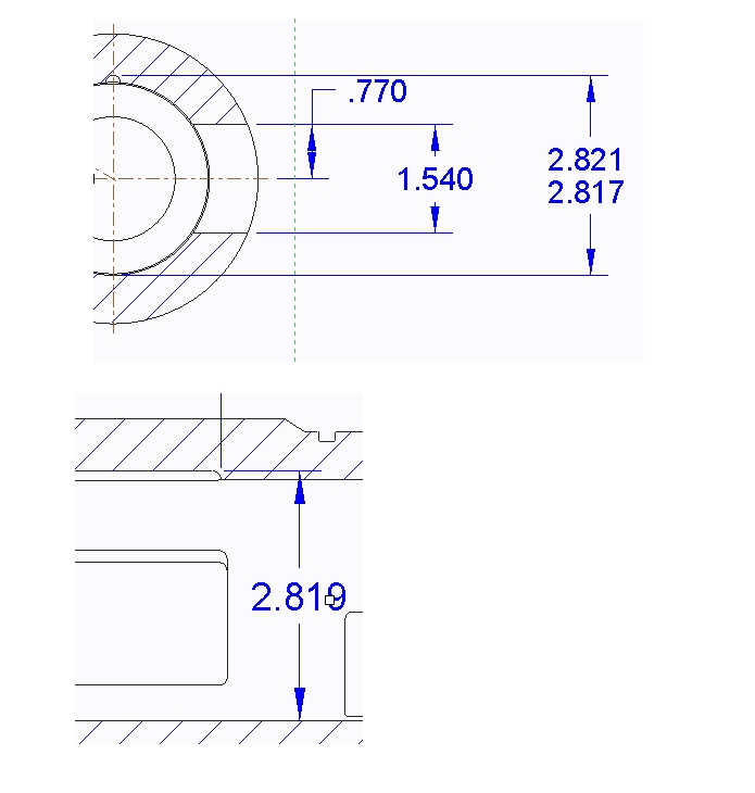
Second question: I need to dimension a keyway cut into my housing from the max of the keyway to the max ID of the bore at the slanted angle that the dimension is. When I try dimensioning the "slanted" option is greyed out. It only want to drop vertical or horizontal. The feature was created using a revolve cut in my part on a plane that is an angle off the axis. There is no way to shown the plane as an axis? Anything? See below
This thread is inactive and closed by the PTC Community Management Team. If you would like to provide a reply and re-open this thread, please notify the moderator and reference the thread. You may also use "Start a topic" button to ask a new question. Please be sure to include what version of the PTC product you are using so another community member knowledgeable about your version may be able to assist.
- Labels:
-
2D Drawing
- Mark as New
- Bookmark
- Subscribe
- Mute
- Subscribe to RSS Feed
- Permalink
- Notify Moderator
Section view.
Create it in the drawing, it is soooooo much easier
select the view > RMB > properties
select sections, select the radio button for 2d cross section, select the green "+"
if there is a section available, it will show up. If not, you can create a new one. should be simple enough from here.
Check out the video
Creating a Section view : PTC Creo - YouTube
Dimension
If you created the cut like you wanted it dimensioned, you should be able to show the model annotations.
- Mark as New
- Bookmark
- Subscribe
- Mute
- Subscribe to RSS Feed
- Permalink
- Notify Moderator
And I always create my sections in my model, I find it easier to select the datum or surface I want my x-sec taken from and also to visualize that it's cutting everything as I want to see it.
This video shows how to create the x-section in the model: Creo 2.0 Sections Part 1 - YouTube
You may want to clarify what dimension you want to see with regards to the keyway. Sometimes I'll use construction lines and points along with constraints in modeling the feature to allow me to get the exact dimensions I want to use in my drawing.
- Mark as New
- Bookmark
- Subscribe
- Mute
- Subscribe to RSS Feed
- Permalink
- Notify Moderator
The attached image shows how we typically dimension our keyways (Top View). The lower image shows how the feature was created. This was done with a revolve cut on a plane therefore there is no angle to show and also no centerline to show. I cannot create a center line this way either. I should mention that I showed a keyway that is vertical. I have others that are off vertical by 20 degree's. These are the ones that I cannot fully dimension. I can't get an angle or a slanted dimension.

- Mark as New
- Bookmark
- Subscribe
- Mute
- Subscribe to RSS Feed
- Permalink
- Notify Moderator
Hi Donald,
As far as sections go, same/same.... It's always easier to create it where you are when you need it.
learn to "love the one your with"
I can think of 3 ways to handle your dimension question
first way (less over head, just one line, in one view, on one sheet, of the drawing)
sketch a line in the drawing....yes I know creo is a beast when it comes to using the drawing sketch tools, but with some practice it works (you should have been here in 1972). The created dimension is a little tricky, first click on the bore then use the intersect of the key-way radius and the sketched line, then click where you want to place the dimension, select tangent then parallel from the drop-down and select the sketched line to set the direction.
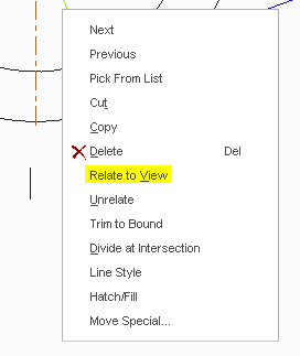
don't forget to do the "relate to view" command found in the right button drop down

second way (more over head, will show up in all your views, it will have to be put on a layer to hide it)
create a sketched line in the model. when you dimension you can click on the bore and then the key-way radius, then click where you want to place the dimension, select tangent_tangent then parallel from the drop down and select the sketched line to set direction.
third way (same issues as second way)
While your in creating the model sketch you could add the reference dimension you seek and then show it in the drawing
as shown in snapshot below, all 3 ways will reward you the same result

Good luck
- Mark as New
- Bookmark
- Subscribe
- Mute
- Subscribe to RSS Feed
- Permalink
- Notify Moderator
Based on what I think you're describing and you need an to create offset section, you sectch the section line on the view you show through the holes or hole and key using the centerlines you created as references, the section is cut along the length of the shaft. In the drawing you create the view with the section and select Aligned as the section option, this will place one feature, hole or key way, at the top of the view and the other at the bottom of the view, features are shown as if the features are180 degrees and not the actual between features. You can then add the section arrow to the cylindrical view. You should be able to show the center axis created by the revolve feature you shouldn't have to create it using the drawing tools.


