
Turn on suggestions
Auto-suggest helps you quickly narrow down your search results by suggesting possible matches as you type.
Showing results for
Turn on suggestions
Auto-suggest helps you quickly narrow down your search results by suggesting possible matches as you type.
Showing results for
- Community
- Creo (Previous to May 2018)
- Creo Modeling Questions
- RE: Gear tooth deflection - shrink fit
Options
- Subscribe to RSS Feed
- Mark Topic as New
- Mark Topic as Read
- Float this Topic for Current User
- Bookmark
- Subscribe
- Mute
- Printer Friendly Page
Gear tooth deflection - shrink fit
May 17, 2011
01:38 PM
- Mark as New
- Bookmark
- Subscribe
- Mute
- Subscribe to RSS Feed
- Permalink
- Notify Moderator
May 17, 2011
01:38 PM
Gear tooth deflection - shrink fit
I need to run an analysis on a gear to see the tooth deflection induced by the shrink fit of the bore on to a shaft. Loading is easy just a simple pressure load applied on the bore, but how do I constrain it properly? I was thinking perhaps using a cyclic constraint? Any ideas?
Thanks,
Chris.
11 REPLIES 11
May 17, 2011
01:45 PM
- Mark as New
- Bookmark
- Subscribe
- Mute
- Subscribe to RSS Feed
- Permalink
- Notify Moderator
May 17, 2011
01:45 PM
Chris,
Try running the model in 1/8 symmetry. The symmetry planes will serve as
your constraints.
You could also try adding either weak springs or I think there is an
inertial relief option for linear simulations.
Steve
Stephen Seymour, P.E.
Principal Engineer
Seymour Engineering & Consulting Group, LLC
3600 NW 138th Street
Suite #102
Oklahoma City, OK 73134
May 17, 2011
04:04 PM
- Mark as New
- Bookmark
- Subscribe
- Mute
- Subscribe to RSS Feed
- Permalink
- Notify Moderator
May 17, 2011
04:04 PM
Running the simulation with a pressure load applied on the bore and selecting the check box for inertial relief under static analysis worked perfect!
Thanks,
Chris.
May 17, 2011
05:04 PM
- Mark as New
- Bookmark
- Subscribe
- Mute
- Subscribe to RSS Feed
- Permalink
- Notify Moderator
May 17, 2011
05:04 PM
looking at the analysis results for stess everything looks as expected... what up with the deflections?
May 17, 2011
05:10 PM
- Mark as New
- Bookmark
- Subscribe
- Mute
- Subscribe to RSS Feed
- Permalink
- Notify Moderator
May 17, 2011
05:10 PM
Artifact of the viewer. Plagues most FEA programs. Linear simulations will
determine the new node locations
for elements. The path is a straight line. Therefore, when animating or
showing scaled up versions of cylindrical
parts the parts may appear to "swell" radially.
It is documented somewhere in the PTC KB.
Stephen Seymour, P.E.
Principal Engineer
Seymour Engineering & Consulting Group, LLC
3600 NW 138th Street
Suite #102
Oklahoma City, OK 73134
May 18, 2011
11:36 AM
- Mark as New
- Bookmark
- Subscribe
- Mute
- Subscribe to RSS Feed
- Permalink
- Notify Moderator
May 18, 2011
11:36 AM
Chris, I'm afraid applying Inertia Relief in this particularsimulation is incorrect.
Inertia relief will apply mass/inertia forces throughout the model to balance the applied pressure, while inreality the pressureshould bebalanced out by the hoop stress alone.
See attached for the details. It will also explain the displacement plot you're observing.
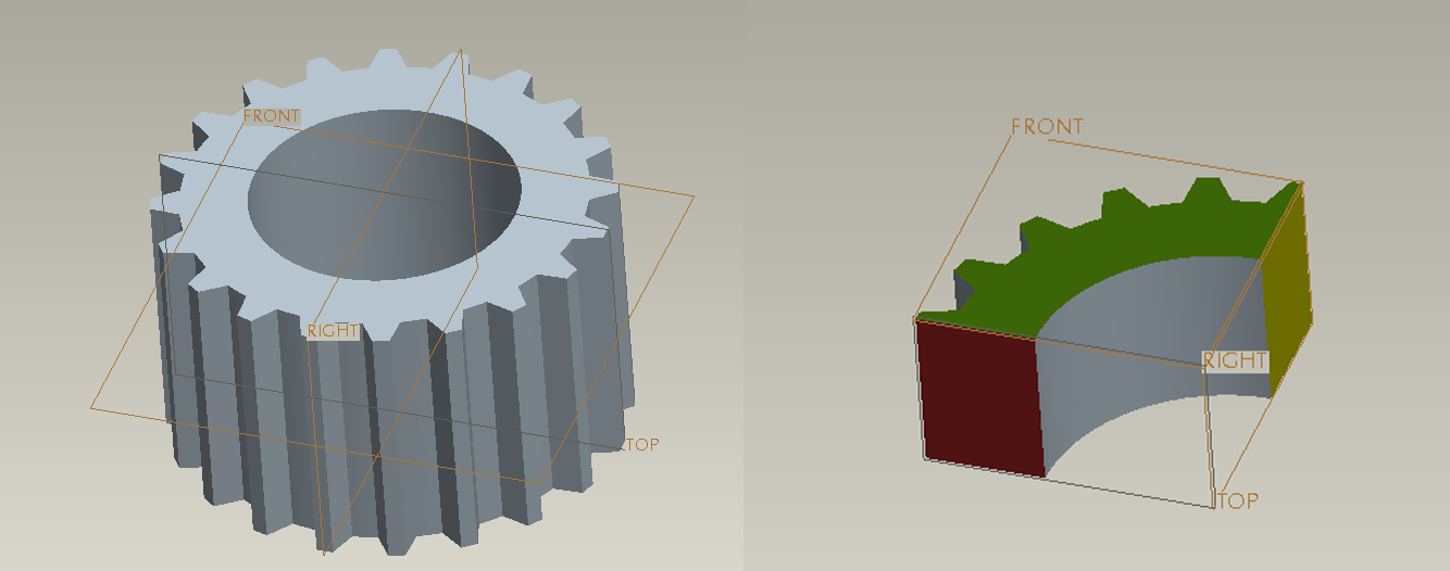
Instead, I'd suggest to use one-tooth model (cut it out from the full model), along with the Cyclic Symmetry. (other options might be to solve 1/4, 1/8, etc models with the proper Mirror Symmetry constraints).
Hope this helps,
Iouri (Yuri) Apanovitch, Ph.D, P.Eng
Inertia relief will apply mass/inertia forces throughout the model to balance the applied pressure, while inreality the pressureshould bebalanced out by the hoop stress alone.
See attached for the details. It will also explain the displacement plot you're observing.
Instead, I'd suggest to use one-tooth model (cut it out from the full model), along with the Cyclic Symmetry. (other options might be to solve 1/4, 1/8, etc models with the proper Mirror Symmetry constraints).
Hope this helps,
Iouri (Yuri) Apanovitch, Ph.D, P.Eng
May 18, 2011
04:32 PM
- Mark as New
- Bookmark
- Subscribe
- Mute
- Subscribe to RSS Feed
- Permalink
- Notify Moderator
May 18, 2011
04:32 PM
I’ve tried this a few different ways and can’t seem to get it right. My initial suggestion using cyclic symmetry is not a valid use of the tool, as I am only able to use it for a model analysis. So if I use a slice of the gear what type of constraint should I be using? Rigidly constraining the sides causes unrealistic stress concentration on those edges.
The last approach I tried was placing weak ground springs at 90 degree intervals on the top and bottom surfaces of the cylindrical feature. I was really surprised to see non-uniform displacement as was seen with using Inertial Relief and just the pressure force. So that appears to get back to what Steve mentioned regarding node locations. However that is confusing as the nodes should be the connection points of the springs. I can understand this while using Inertial Relief as the system chooses constraint point arbitrarily.
Still is it not possible to do an analysis on a pressure vessel? That’s essentially the problem, as Yuri pointed out the force is internal pressure the constraint is the hoop stress. But how can it be simulated in Mechanica?
Thanks,
Chris.
May 18, 2011
04:45 PM
- Mark as New
- Bookmark
- Subscribe
- Mute
- Subscribe to RSS Feed
- Permalink
- Notify Moderator
May 18, 2011
04:45 PM
For your gear problem try creating a 1/8th symmetry model. On the symmetry
(or slice) surfaces place a symmetry constraint.
The symmetry constraint is analogous to constraining all displacement normal
to the symmetry surface. You will then have
a fully constrained model without the constraints influencing the results.
Using symmetry is how you would do a pressure vessel as well, assuming there
are no external frame connections.
Stephen Seymour, P.E.
Principal Engineer
Seymour Engineering & Consulting Group, LLC
3600 NW 138th Street
Suite #102
Oklahoma City, OK 73134
May 18, 2011
05:32 PM
- Mark as New
- Bookmark
- Subscribe
- Mute
- Subscribe to RSS Feed
- Permalink
- Notify Moderator
May 18, 2011
05:32 PM
This is an easy problem.
Rather than using the 'inertial relief' or 'cyclic symmetry' you would be
better off using a pie slice with 'reflected symmetry' boundary conditions
and a soft spring to keep it from moving in the axial direction. The rule
for reflected symmetry on a solid model is that the displacements in a
direction normal to the symmetry plane are fixed and the displacements in
the plane of symmetry are free. It would be easiest if you created a
cylindrical coordinate system, then constrain only the tangential
displacements on the two symmetry planes.
Displacements need a frame of reference and with inertial relief the frame
of reference is not explicitly defined. Cyclic symmetry is for problems
that have patterns of geometry and loads that are repeated about an axis.
If you had a tangential load on every tooth or if you had a blade of a
turbine or fan you would use cyclic symmetry.
If you are trying to model a shrink fit you may be better off modeling both
parts and using contact between the two. This would give you a much more
realistic load distribution rather than assuming a uniform pressure load.
Generally you can model interference directly and Mechanica will deform the
parts to fit when it runs however if the interference is very small you may
need to model both diameters equal and use the CTE of the shaft material
along with a temperature load to get the shaft to expand. I would try it
the first way first.
Good luck.Jim Holst
May 18, 2011
05:36 PM
- Mark as New
- Bookmark
- Subscribe
- Mute
- Subscribe to RSS Feed
- Permalink
- Notify Moderator
May 18, 2011
05:36 PM
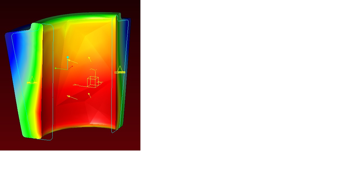
Thank-you for the information! I tried setting up the system as you’ve suggested, I’ve a 90 degree piece constrained on the symmetry surfaces. On one surface constrained X and Z, the other Y and Z, rotations are free. The displacement is closer to what I would expect, as you can see from the displacement picture, it expands radially but since it’s constrained on Z there is no deformation from top to bottom.
So I removed the Z constraint on those surfaces and placed 4 weak ground springs; the pressure load is 4500psi the springs have a stiffness value of 1 lbf/in (extensional), 1 in*lbf/rad (torsional). Looks good, is it valid? ...I think so. comments?
Thanks,
Chris.
May 18, 2011
05:55 PM
- Mark as New
- Bookmark
- Subscribe
- Mute
- Subscribe to RSS Feed
- Permalink
- Notify Moderator
May 18, 2011
05:55 PM
Chris,
One option instead of using the weak springs, you could place a constrain on
either the top or bottom surface to constrain motion in the vertical
direction. However, do not place the vertical constraint on both. (see
attached). This would be an alternative if the springs were creating
localized stresses or causing some sort of other problem.
Also, for meshes containing solid elements (shown in blue) there is no need
to constrain or unconstrain the degrees of freedom associated with rotation.
Solid elements only support translations. However, beams, shells, and
springs do support 6 DOF (3 translation and 3 rotation).
Other than that the deformation pictures seem reasonable given the tapered
design. I don't know what the magnitudes are and if they are correct, but I
am sure you can lean on some prior product data at your facility.
Steve
Stephen Seymour, P.E.
Principal Engineer
Seymour Engineering & Consulting Group, LLC
3600 NW 138th Street
Suite #102
Oklahoma City, OK 73134
May 19, 2011
10:09 AM
- Mark as New
- Bookmark
- Subscribe
- Mute
- Subscribe to RSS Feed
- Permalink
- Notify Moderator
May 19, 2011
10:09 AM
Chris,
Cyclic symmetry on a "pie slice" model in case of a strictly radial load/deformation (as in your case) is equivalent to the"reflective/mirror symmetry", so I'm not sure why it's not working for you, perhaps there's something else that's missing in your model. (Note that "reflective symmetry" couldn't replace "cyclic symmetry" if a tangential load was applied, as Jim Holst correctly points out.)
However, that's not really important. If 1/4 model withmirror symmetry works for you, that's perfectly fine.
The rest -- just minimally constrain the model in axial direction, as Stephen Seymour recommends, no need to use springs or overconstrain by applying on both sides.
Regards,
Yuri
