
Turn on suggestions
Auto-suggest helps you quickly narrow down your search results by suggesting possible matches as you type.
Showing results for
Turn on suggestions
Auto-suggest helps you quickly narrow down your search results by suggesting possible matches as you type.
Showing results for
Community Tip - Need to share some code when posting a question or reply? Make sure to use the "Insert code sample" menu option. Learn more! X
- Community
- Creo (Previous to May 2018)
- Creo Modeling Questions
- Mesh of revolution
Options
- Subscribe to RSS Feed
- Mark Topic as New
- Mark Topic as Read
- Float this Topic for Current User
- Bookmark
- Subscribe
- Mute
- Printer Friendly Page
Mesh of revolution
Jan 11, 2016
11:20 AM
- Mark as New
- Bookmark
- Subscribe
- Mute
- Subscribe to RSS Feed
- Permalink
- Notify Moderator
Jan 11, 2016
11:20 AM
Mesh of revolution
There is no a command that permit to you to do a mesh of revolution using the "advanced tool" introduced with the Creo release: the mapped mesh option and the prismatic element option.
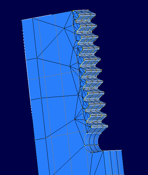
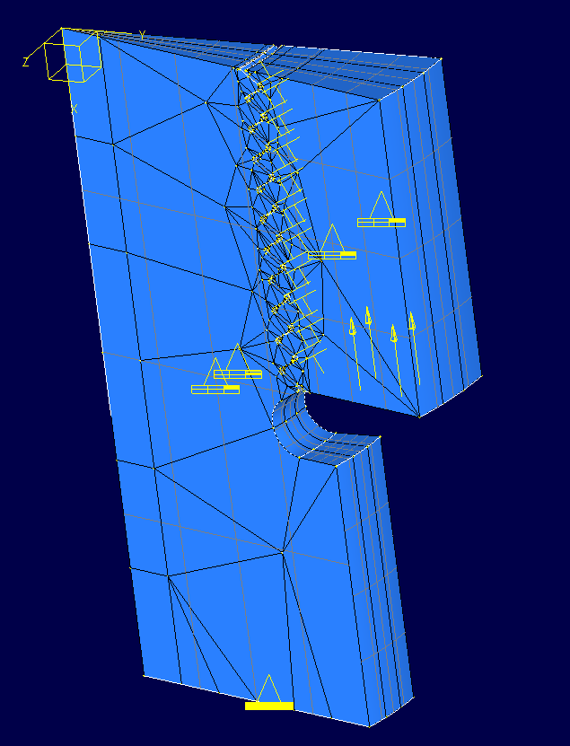
For example, I'm trying to do a 3d mesh on this quarter of screw.
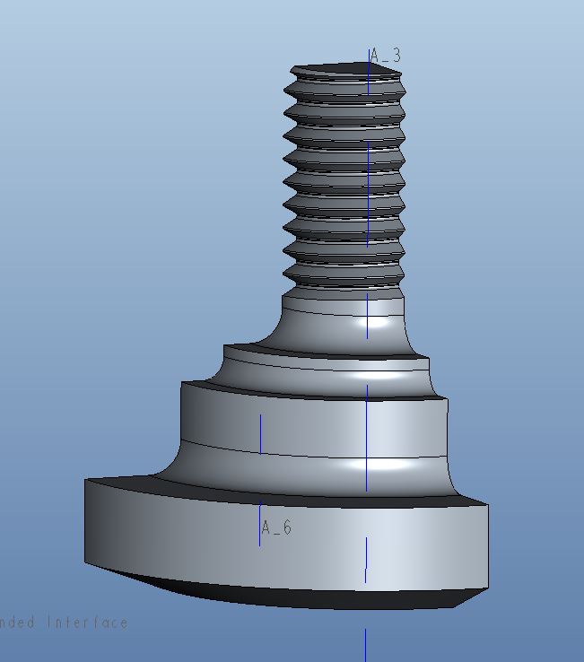
How can I do otherwise?
Thanks.
21 REPLIES 21
Jan 11, 2016
01:58 PM
- Mark as New
- Bookmark
- Subscribe
- Mute
- Subscribe to RSS Feed
- Permalink
- Notify Moderator
Jan 11, 2016
01:58 PM
Hi,
Similar was discussed in the following thread with some reasonable (?) conclusions
Your thread is a helix though. You would have to compromise and make the thread a revolve.
Regards
Jan 12, 2016
02:48 AM
- Mark as New
- Bookmark
- Subscribe
- Mute
- Subscribe to RSS Feed
- Permalink
- Notify Moderator
Jan 12, 2016
02:48 AM
This was possible in the old Mechanica Independent mode... But as Charles pointed out, you would then have to compromise and make the thread as a revolve,not a helix. And if you do a revolve, then I'd model it one element thick, as an "almost 2D"-model. And if you do that, no element can touch the revolve axis at a corner; all elements must have an edge along the revolve axis. There are no elements that describe the shape of a triangle or quad revolved around an axis that intersects only a corner of that tri/quad.
Jan 12, 2016
03:09 AM
- Mark as New
- Bookmark
- Subscribe
- Mute
- Subscribe to RSS Feed
- Permalink
- Notify Moderator
Jan 12, 2016
03:09 AM
Hi,
I've already done the 2d axisymmetric analysis (with contact) and now I try to do the same within the 3D environment.
Allow to the mesh engine the task of making the mesh is not the right way, for me, because it generates a tetra mesh; this means:
- high number o elements
- tetra elements are not the best choice for contact analysis
- much time for results
But this geometry is not simple...
Ah...I'm using Creo 3.
Jan 12, 2016
03:15 AM
- Mark as New
- Bookmark
- Subscribe
- Mute
- Subscribe to RSS Feed
- Permalink
- Notify Moderator
Jan 12, 2016
03:15 AM
That makes sense, but in 2D you can not, at least in Creo 2, combine plasticity, large deformations and contact. Large deformations is necessary in this case since it is a statically indeterminate problem - many contacts share the contact load. If you use small deformation theory, contact forces will be wrong.
Jan 12, 2016
04:31 AM
- Mark as New
- Bookmark
- Subscribe
- Mute
- Subscribe to RSS Feed
- Permalink
- Notify Moderator
Jan 12, 2016
04:31 AM
In Creo 3 you can use large deformation and contact within 2d analysis.
I've not tried with a plastic material...
Returning to the main argument, the meshing operation is not simple and it is not supported by adequate tools.
Jan 12, 2016
12:31 PM
- Mark as New
- Bookmark
- Subscribe
- Mute
- Subscribe to RSS Feed
- Permalink
- Notify Moderator
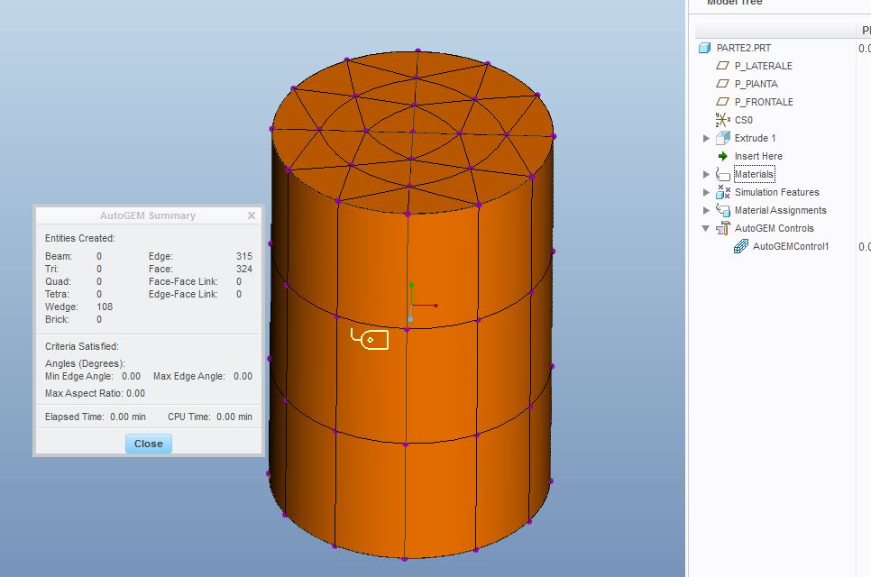
Jan 12, 2016
12:31 PM
I can't go on...the mesh within the part it's ok but when I do the mesh in the assembly it fails...
It's done with Creo 3.
Jan 12, 2016
02:25 PM
- Mark as New
- Bookmark
- Subscribe
- Mute
- Subscribe to RSS Feed
- Permalink
- Notify Moderator
Jan 12, 2016
02:25 PM
Giulio,
I took a quick look at your model and feel somewhat responsible for the link I posted with a 'methodology'.
You will struggle with this. I believe you are right, this should be easy but it is not. Despite the methodology it disappoints and the effort required is disproportionate.
The BRICK part meshes but gives >1100 face-face links too. This slows things up. we should avoid links.
I can see that you want a regular mesh at the interfaces to get good contact results.
Can you describe your objective in more detail? Sharing this may help the more seasoned of us here to find a reasonable path that avoids your frustrations.
Thanks
Charles
Jan 12, 2016
04:14 PM
- Mark as New
- Bookmark
- Subscribe
- Mute
- Subscribe to RSS Feed
- Permalink
- Notify Moderator
Jan 12, 2016
04:14 PM
I want to see if the manual calculation is equal to the one in 2d and in 3d.
I've already verified the first two and are similar.
With the last, 3d, I want to do it with the most regular mesh possible also for make practice with the mapped mesh tool.
Now, I don't understand why if you open the bottom part that I've mesh and you let make the mesh, it works; but if you try the same within the assembly, it gives error.
And this happens also if you let make the mesh for component instead on the entire assembly.
I've tried changing the tolerances within the mesh options, but nothing...
Jan 13, 2016
04:54 AM
- Mark as New
- Bookmark
- Subscribe
- Mute
- Subscribe to RSS Feed
- Permalink
- Notify Moderator
Jan 13, 2016
04:54 AM
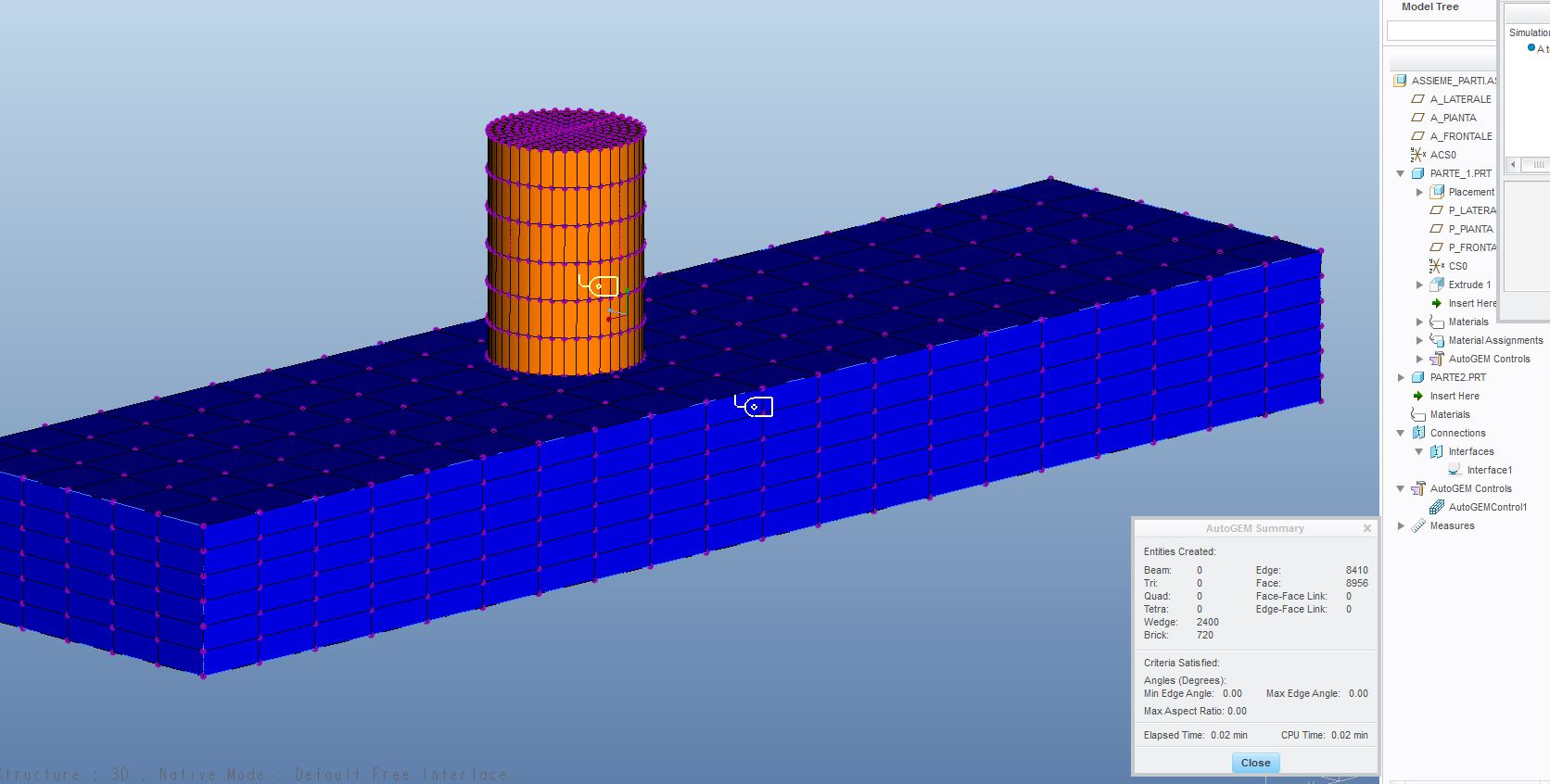
This morning I've tried make a new assembly of test, with 2 simple parts; each of them has been mesh separately inside of own part.
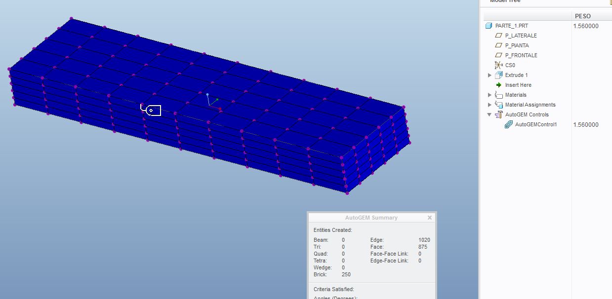
Results: while each part has been mesh correctly by the own mapped mesh tool, within the assembly the "sub tool of mapped mesh" doesn't work.
Appear a little yellow triangle near the command.
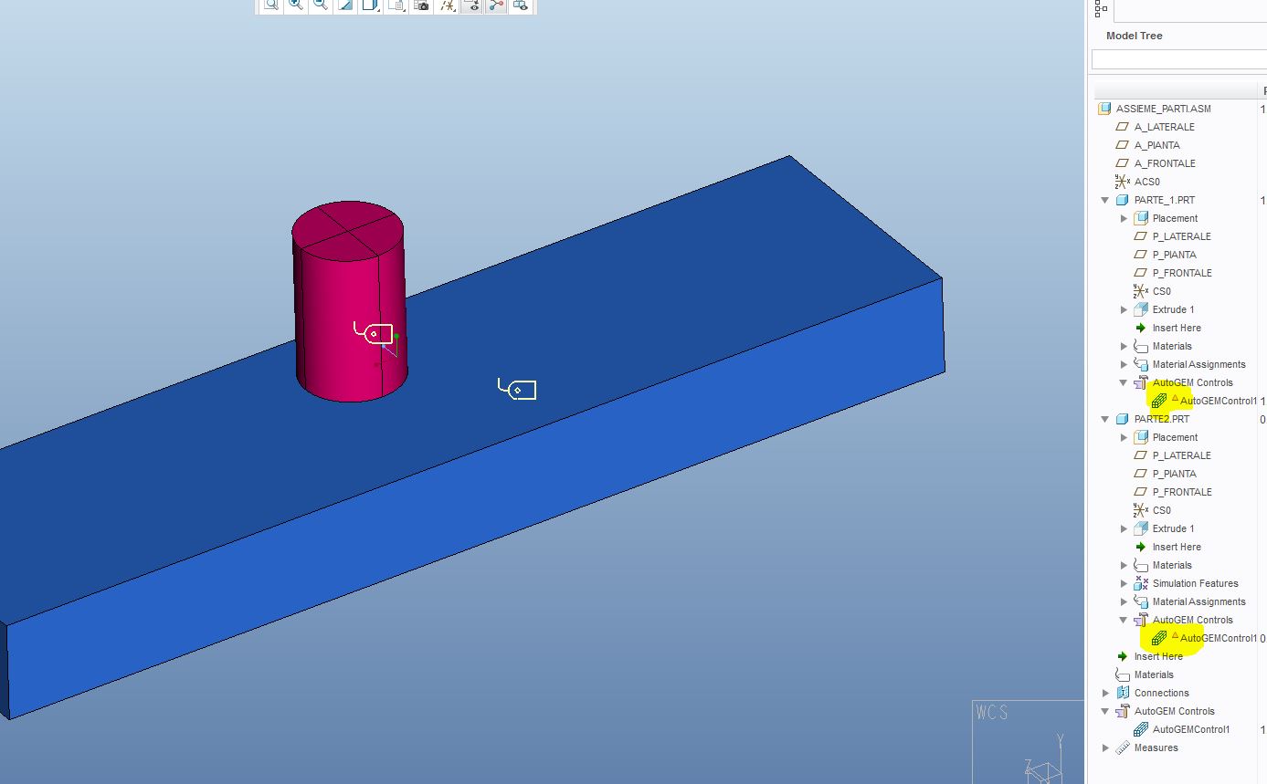
There is a manner that permit to you to "resume" the mapped mesh inside each parts? Some option. Or you must, always, make a giant mapped mesh in the main assembly?
Jan 13, 2016
06:13 AM
- Mark as New
- Bookmark
- Subscribe
- Mute
- Subscribe to RSS Feed
- Permalink
- Notify Moderator
Jan 13, 2016
06:13 AM
Ah yes,
Mapped mesh controls are suppressed if defined at part level. Only the Assy level mapped mesh controls work.
I can't remember if the behaviour is the same with prismatic elements & thin.
Other mesh controls work if defined at part level,
What I will say is that it is possible to get reasonable pressure plots with tets now with the right refinement. This applies equally to a regular mesh. I have examples somewhere.
I will have a look at your other info in more detail later.
What is you manual calculation calculating?
Regards
Jan 13, 2016
06:51 AM
- Mark as New
- Bookmark
- Subscribe
- Mute
- Subscribe to RSS Feed
- Permalink
- Notify Moderator
Jan 13, 2016
06:51 AM
I remembered wrong.
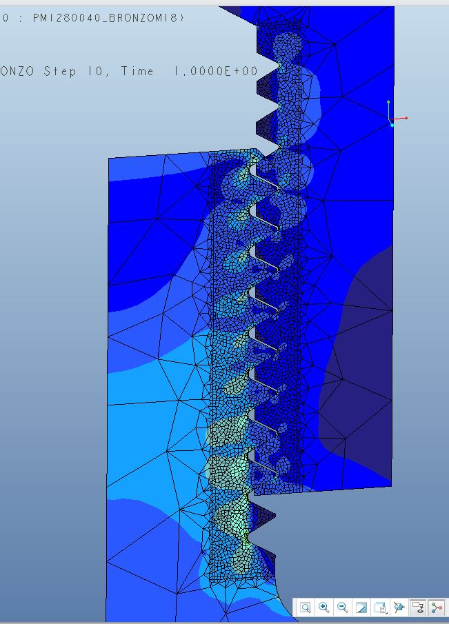
I've accosted two different values: the value of VM stress on the resistant diameter and at the center of the first fillet, manually calculated considering that the first fillet absorbs about 38% of the force-> 150 MPa
and the value of the 2d analysis of 180 MPa, always on the first fillet, but not at the same place, but on the radius between the 1° and 2° fillet, where you have a concentration of stress.
In the same place I would have 50 MPa.
One more reason for studying the argument.
Jan 13, 2016
06:24 AM
- Mark as New
- Bookmark
- Subscribe
- Mute
- Subscribe to RSS Feed
- Permalink
- Notify Moderator
Jan 13, 2016
06:24 AM
I have not looked at all the details above, but Iknow that, at least in Creo 2, mesh controls created on part level are ignored in assembly mode.
Is a "revolve" approximation of the helical thread OK?
Jan 13, 2016
07:58 AM
- Mark as New
- Bookmark
- Subscribe
- Mute
- Subscribe to RSS Feed
- Permalink
- Notify Moderator
Jan 13, 2016
07:58 AM
I've made a helicoidal sweep despite in some paper you read that also using a simple "revolve feature" the results doesn't vary significantly.
But I have yet to test it.
Jan 13, 2016
09:35 AM
- Mark as New
- Bookmark
- Subscribe
- Mute
- Subscribe to RSS Feed
- Permalink
- Notify Moderator
Jan 13, 2016
09:35 AM
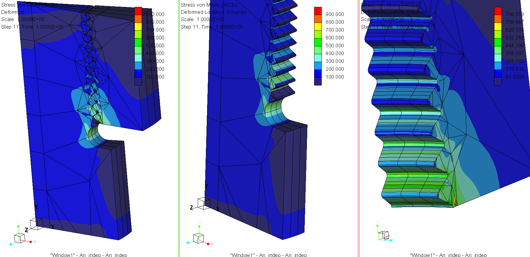
Here's an attempt created in Mechanica Independent Mode (version Creo 2.0)
I had a convcergence issue for the first load step (rigid body motion) so instead I created an enforced displacement. For some reason, I get an error message when I post-process in independent mode, so I did the stress plot from within regular Creo Simulate.
All elements are brick/ wedge. To save time, I only ran a P-level 3 quick check. In Mechanica Independent mode this is done by first creating a surface mesh (quad/tri shell elements). Then I revolve these into brick/wedge elements. This is only possible for a revolved thread, not the helical one.
Jan 15, 2016
09:03 AM
- Mark as New
- Bookmark
- Subscribe
- Mute
- Subscribe to RSS Feed
- Permalink
- Notify Moderator
Jan 15, 2016
09:03 AM
Mats I've tried doing a solid analysis of a portion of 15 degrees like yours, but with helical sweep.
In this case I didn't use a mapped mesh but the classic tetras.
I don't understand why the analysis doesn't converge at the first step.
I've tried to vary different parameters in the analysis' tab.
Also the case with the cut at 90° returns the same things...
Jan 16, 2016
04:37 AM
- Mark as New
- Bookmark
- Subscribe
- Mute
- Subscribe to RSS Feed
- Permalink
- Notify Moderator
Jan 16, 2016
04:37 AM
The most likely reason why the solution does not converge at the first step is that there is a clearance between contact surfaces. This means that there needs to be rigid body motion before there are any contact forces. This is difficult for the solver. Move one component closer, or so that contact surfaces touch each other at t=0.
It's also an option to use prescribed motion instead of applied force. This is how I did it. Create a constraint that moves one component, and a force measure to keep tracj of the force.
Jan 16, 2016
08:20 AM
- Mark as New
- Bookmark
- Subscribe
- Mute
- Subscribe to RSS Feed
- Permalink
- Notify Moderator
Jan 16, 2016
08:20 AM
I've checked the assembly and there isn't interferences and the geometries are in contact.
Happens that, especially in a nonlinear analysis, you have to get "the input of the contact" with one imposed displacement; and I had tried, but it didn't work.
When I will return at work I will try to do a simple cylindrical sweep instead of a helical one. Maybe it will work with the same configuration....
Jan 20, 2016
02:22 AM
- Mark as New
- Bookmark
- Subscribe
- Mute
- Subscribe to RSS Feed
- Permalink
- Notify Moderator
Jan 20, 2016
02:22 AM
I've done a simple revolve assembly, meshed with tetras and contacts with finite friction; cyclic symmetry constraint.
As in the helical assembly, the analysis doesn't converge at the beginning.
I noted that in reality the analysis doesn't converge only at the 2° pass of the Single Pass Analysis.
The 1° pass, where all the p-elements have a polynomial of third degree, has always been completed.
I've tried analysis with:
- Automatic steps within range
- User-defined output steps
- 20 and 40 steps
- Auto definition of steps
- user definition of time step with the first 10 pass very small
but the result is always the same: the quick check analysis goes and in the single pass goes only the 1° pass.
Jan 20, 2016
04:08 AM
- Mark as New
- Bookmark
- Subscribe
- Mute
- Subscribe to RSS Feed
- Permalink
- Notify Moderator
Jan 20, 2016
04:08 AM
I too often find that it is difficult for the solver to converge at pass 2 for nonlinear problems. The workaround I use is to run a quick-check with a fine mesh.
Jan 20, 2016
04:26 AM
- Mark as New
- Bookmark
- Subscribe
- Mute
- Subscribe to RSS Feed
- Permalink
- Notify Moderator
Jan 20, 2016
04:26 AM
It would be fine if PTC explain why this happens...
Anyway I think your workaround is the best choice.
For the choice of the time step, which of the many options do you prefer and in which cases?
Jan 20, 2016
09:36 AM
- Mark as New
- Bookmark
- Subscribe
- Mute
- Subscribe to RSS Feed
- Permalink
- Notify Moderator
Jan 20, 2016
09:36 AM
As for the time step, I don't know what's optimal. This is problem dependent. My first choice is to pick so many time steps as I want results. If that is too coarse for the solver, then the solver automatically adjust the time step, but you get faster convergence if you choose a time step in the first place, that is sufficiently small for the solver to converge. Then you save the time it takes for the solver to try those too big steps. Note also that some time steps may be easier for the solver than others; that depends on what happens in the model.
