Community Tip - Want the oppurtunity to discuss enhancements to PTC products? Join a working group! X
- Community
- Creo+ and Creo Parametric
- Analysis
- Create 2D layout/sketches in 3D environment
- Subscribe to RSS Feed
- Mark Topic as New
- Mark Topic as Read
- Float this Topic for Current User
- Bookmark
- Subscribe
- Mute
- Printer Friendly Page
Create 2D layout/sketches in 3D environment
- Mark as New
- Bookmark
- Subscribe
- Mute
- Subscribe to RSS Feed
- Permalink
- Notify Moderator
Create 2D layout/sketches in 3D environment
Hi all, good day.
I am creating 2D sketches/layout in the Part (.prt) environment. This allow me to stack different component sketches in just a lightweight file, and all I need is to visualize the interference among these stacked-up sketches.
All went well so far, the only problem is that I need to manipulate/edit each sketch with extra caution, due to the large quantities of dimensions and relations showing in edit mode. Anyone know a Pro/engineer function that can group a 2D sketch under a block and locking all dimensions (and perhaps relations as well)?
This would be similar to the AutoCAD block feature, where we can move the block freely to anywhere, and explode the block when need to edit a particular set of dimensions.
This thread is inactive and closed by the PTC Community Management Team. If you would like to provide a reply and re-open this thread, please notify the moderator and reference the thread. You may also use "Start a topic" button to ask a new question. Please be sure to include what version of the PTC product you are using so another community member knowledgeable about your version may be able to assist.
Solved! Go to Solution.
- Labels:
-
General
Accepted Solutions
- Mark as New
- Bookmark
- Subscribe
- Mute
- Subscribe to RSS Feed
- Permalink
- Notify Moderator
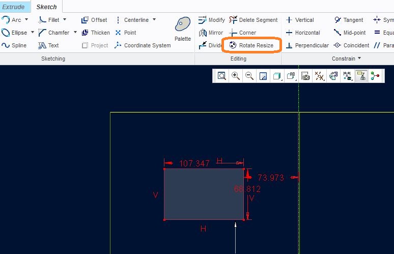
Using Rotate Resize command in sketcher you can control your entities in such a way that they seem to be in a block, without extra caution.

- Mark as New
- Bookmark
- Subscribe
- Mute
- Subscribe to RSS Feed
- Permalink
- Notify Moderator
You could try using symbols
In the symbols, you can create variable text
You could even create variable "imagery"
refer to the surface finish symbols
- Mark as New
- Bookmark
- Subscribe
- Mute
- Subscribe to RSS Feed
- Permalink
- Notify Moderator
Thanks for the feedback, Ron.
I have been using the symbols in the Drawing (.drw) file, it is a very nice tool; but the use of symbols doesn't reflect the actual sketch dimension, or allow the designer/user to edit the sketch lines. I am not sure if 3D symbols work well in this case either.
I have attached below screen shot for better understanding about what I am working on.
- Mark as New
- Bookmark
- Subscribe
- Mute
- Subscribe to RSS Feed
- Permalink
- Notify Moderator
So how does this sketch differ from another sketch? I'm not grasping the concept you are attempting.
From what I am gathering so far, it seems you are trying to put multiple parts inside one file.
Perhaps a family table might work
ron
- Mark as New
- Bookmark
- Subscribe
- Mute
- Subscribe to RSS Feed
- Permalink
- Notify Moderator
Using Rotate Resize command in sketcher you can control your entities in such a way that they seem to be in a block, without extra caution.

- Mark as New
- Bookmark
- Subscribe
- Mute
- Subscribe to RSS Feed
- Permalink
- Notify Moderator
Hi James, I guess the Rotate Resize feature is only available to CREO Parametric or newer version.
This might be the easiest way to manipulate dropped sketches. Thanks for sharing.
- Mark as New
- Bookmark
- Subscribe
- Mute
- Subscribe to RSS Feed
- Permalink
- Notify Moderator
Hi,
It's and object-action only type of command. Meaning, you have to preselect some entities first, then it won't be greyed out.
- Mark as New
- Bookmark
- Subscribe
- Mute
- Subscribe to RSS Feed
- Permalink
- Notify Moderator
Hi James, thanks for the point out.
I just found the Rotate Resize command, and I could use it along with Dynamic Edit.


