Community Tip - Did you know you can set a signature that will be added to all your posts? Set it here! X
- Community
- Creo+ and Creo Parametric
- Analysis
- Re: Example door hinge mechanism with two hinges, ...
- Subscribe to RSS Feed
- Mark Topic as New
- Mark Topic as Read
- Float this Topic for Current User
- Bookmark
- Subscribe
- Mute
- Printer Friendly Page
Example door hinge mechanism with two hinges, stiffness and no redundancies. (advanced hinge)
- Mark as New
- Bookmark
- Subscribe
- Mute
- Subscribe to RSS Feed
- Permalink
- Notify Moderator
Example door hinge mechanism with two hinges, stiffness and no redundancies. (advanced hinge)
This article describes a solution to use when it is desired to have 2 "concentric" pin joints but that causes redundancies and improper load transfer.
Some application examples are a door with two "hinges" or a loader/excavator with two arms out to the bucket.
The attached example includes static analysis showing the amount of load on the individual pin joints.
It also includes the ability to model joint stiffness via springs.
The ability of the joint to "flex" is what removes the redundancies.
This model has both hinges modeled with cylindrical joints and springs to allow shared UP/DOWN load bearing, However, a simpler version would be to change one to a PIN, then that one would bear the full UP/DOWN load alone. (remove the springs on the cylinder translation as well) That simpler model would work with Force Balance whereas the attached example uses Static analysis due to the additional degrees of freedom UP/DOWN that are absorbed by the translational springs.

I welcome any comments or suggestions / examples that are similar.
- Mark as New
- Bookmark
- Subscribe
- Mute
- Subscribe to RSS Feed
- Permalink
- Notify Moderator
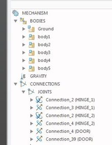
Hi, I don't understand why you talk about redundancies: you have 5 bodies, 4 pins and 2 cylinders. So 6x5-(4x5+2x4) = 2 dofs.
Indeed we have the rotation and the translation (few mm..).
Do I miss something?
We don't have redundancies properly because we have two dofs. Correct?
- Mark as New
- Bookmark
- Subscribe
- Mute
- Subscribe to RSS Feed
- Permalink
- Notify Moderator
Redundancies are about being statically undetermined not about DOF.
Get redundancies from Measures - System - Redundancies = 0
Get DOF from Measures - System - DOF
My example is one solution to the incorrect use of 2 pin joints to connect the door.
A "basic" hinge for this would use just 1 pin joint.
However the basic hinge would not be able to distinguish between a centered load and offset load. It would not show us the load on each separate hinge. (think of a pin joint as infinitely long)
To do this I introduce via dummy bodies, 2 additional rotational DOF at each "hinge" plus 1 translational DOF between the two "hinges"
You could also compare this to using bushings to model joint stiffness, however bushings will not work in kinematic or with drag.
Seemingly redundant systems can be modeled in MDO if the stiffnesses of joints or even bodies are modeled in some way. We are essentially "relaxing" the rigid body assumption a little bit to allow joints to flex into position. The extra bodies and joints added to my door model are like modelling a little flex in the hinges and/or door.
Anyway I hope this helps better explain my model and the reasons for it.


