Community Tip - Did you get called away in the middle of writing a post? Don't worry you can find your unfinished post later in the Drafts section of your profile page. X
- Community
- Creo+ and Creo Parametric
- Analysis
- Self-weight in CREO Simulate
- Subscribe to RSS Feed
- Mark Topic as New
- Mark Topic as Read
- Float this Topic for Current User
- Bookmark
- Subscribe
- Mute
- Printer Friendly Page
Self-weight in CREO Simulate
- Mark as New
- Bookmark
- Subscribe
- Mute
- Subscribe to RSS Feed
- Permalink
- Notify Moderator
Self-weight in CREO Simulate
Greetings! I would like to know if the self-weight of the simulated component needs to be inserted as a load or does it insert it automatically. For example, to calculate the displacement in a beam, would i need to input the weight of the beam as a load? I'm trying to simulate a beam and compare with hand calculations (verification), but I can't get an agreement between the results.
Solved! Go to Solution.
Accepted Solutions
- Mark as New
- Bookmark
- Subscribe
- Mute
- Subscribe to RSS Feed
- Permalink
- Notify Moderator
Correct, by default there is no self-weight loading. Can you screenshot your CREO boundary conditions on the beam and show us the textbook model of the beam you are trying to correlate?
- Mark as New
- Bookmark
- Subscribe
- Mute
- Subscribe to RSS Feed
- Permalink
- Notify Moderator
Creo of course knows the mass, but it does not know the direction nor the amount of gravitational acceleration until you tell it.
Add the appropriate gravity load to your load set.
- Mark as New
- Bookmark
- Subscribe
- Mute
- Subscribe to RSS Feed
- Permalink
- Notify Moderator
Thank you for the answer! Therefore, if I don't add the gravitational load, the mass won't interfere with the simulation?
- Mark as New
- Bookmark
- Subscribe
- Mute
- Subscribe to RSS Feed
- Permalink
- Notify Moderator
Correct, by default there is no self-weight loading. Can you screenshot your CREO boundary conditions on the beam and show us the textbook model of the beam you are trying to correlate?
- Mark as New
- Bookmark
- Subscribe
- Mute
- Subscribe to RSS Feed
- Permalink
- Notify Moderator
Thank you again for the answer!
To try to simulate the supports correctly, I chose to add holes in a 1100mm beam. As the holes are 50mm from the edges, the distance between them is 1000mm. After that, I applied the constraints represented in the image below, to make it similar to the calculation performed. However, for a diameter of 25mm I even achieved a good result, but when I increased it to 50mm the values were very different, which made me think it was just a coincidence.
- Mark as New
- Bookmark
- Subscribe
- Mute
- Subscribe to RSS Feed
- Permalink
- Notify Moderator
Ok, I see the issue. Your constraints are also stopping rotation, so it is not a simply supported beam. You can use the PIN constraint from the menu to allow rotation on the left hole, but the right end that is also free in X is a bit more complex with the hole method. This PIN constraint does not correctly represent the local contact stresses of a pin, but should give you pretty close to a simply supported beam situation. On the right end you need to create a point at the center of the hole and constrain that instead. Then add a rigid to tie that point to the inside surface of the hole. Finally a constrain must be attached to an element so make a dummy spring from the constrained center point connected to ground (or some other point on an element or constraint) with a small stiffness like 1N/mm. The larger you make the hole the less this represents the correct beam geometry from the textbook. Also, keep in mind that textbooks do not consider the Poisson's ratio effect. In your material set Poisson's ratio to 0 (zero) to better match textbook.
Another way to do simply supported is to not have holes, have the correct beam length and constrain the bottom end edges. In this case your constraints would have been correct since now the edge can rotate like a pin. The issue with that way is there is a stress singularity at the edge.
It is a bit confusing when constraining a 3d surface that the rotational DOFs are shown in the dialog. Those are ignored because there is no rotational DOF. When constraining a single point, all 6 DOF are considered in the dialog. When constraining a straight edge, after constraining 3 translations there is only one rotational DOF that can be considered (around the "axle" of the straight line) It would be nice if Creo automatically greyed out the unconsidered DOF options to make it clearer.
Please also look in Creo help for the Simulation Verification Guide.
There you will find many examples for verifying Creo simulate regarding beams under varying conditions. There is also explanations of this Poisson's ratio issue as well as the singularities that might be created.
When installing Creo you can also choose an option to also install the verification models.
For my version they are in the folder C:\Program Files\PTC\Creo 10.0.2.0\Common Files\applications\simulate\ms_verf\.
This will allow you to open the actual model used as well as open the result files to see the plots.
- Mark as New
- Bookmark
- Subscribe
- Mute
- Subscribe to RSS Feed
- Permalink
- Notify Moderator
Best regards! I tested something similar some time ago (PDF attached).
PS: the verification models xxx.mdb are only for MECHANICA? 🤔
- Mark as New
- Bookmark
- Subscribe
- Mute
- Subscribe to RSS Feed
- Permalink
- Notify Moderator
Creo 10 has the part files and then the study result folders.
It is nice when users start with trying to understand the fundamentals. On the old hardware/software systems we were forced to simplify and use fundamentals but the modern capabilities makes it too easy to skip those baby steps.
- Mark as New
- Bookmark
- Subscribe
- Mute
- Subscribe to RSS Feed
- Permalink
- Notify Moderator
Nice!
Yes, I'm trying to understand the fundamentals, so I can make simulations more responsibly.
- Mark as New
- Bookmark
- Subscribe
- Mute
- Subscribe to RSS Feed
- Permalink
- Notify Moderator
Very cool, thank you for share this with us!
- Mark as New
- Bookmark
- Subscribe
- Mute
- Subscribe to RSS Feed
- Permalink
- Notify Moderator
I understand, thanks for all the help!
Therefore, after I input the pin constraint, and the point with rigid link with the other hole, should I input a constraint to the point too?
I don't understand the "dummy spring", what is it?
And thanks for the tips about Creo don't automatically greyed out the unconsidered DOF options! It's clearer to me now how it works.
The .pdf below show the new results. An error of 9% was obtained.
- Mark as New
- Bookmark
- Subscribe
- Mute
- Subscribe to RSS Feed
- Permalink
- Notify Moderator
Hi,
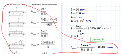
You use Bernoulli's theory
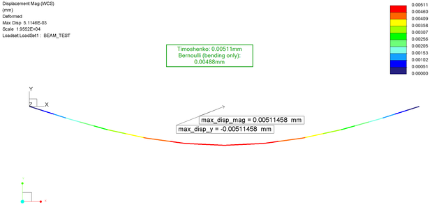
Simulate uses Timoshenko beam (Example attached), that is more accurate
- Mark as New
- Bookmark
- Subscribe
- Mute
- Subscribe to RSS Feed
- Permalink
- Notify Moderator
- Mark as New
- Bookmark
- Subscribe
- Mute
- Subscribe to RSS Feed
- Permalink
- Notify Moderator
Thanks @skunks . I knew Creo Simulate was more accurate than 8% with beams and was looking around trying to find the more accurate beam hand calculations. I did not remember about Timoshenko, but that was the kind of answer I was expecting this to be. If I had looked closer at the Creo verification guide, it is all there.


