
Turn on suggestions
Auto-suggest helps you quickly narrow down your search results by suggesting possible matches as you type.
Showing results for
Turn on suggestions
Auto-suggest helps you quickly narrow down your search results by suggesting possible matches as you type.
Showing results for
Community Tip - Stay updated on what is happening on the PTC Community by subscribing to PTC Community Announcements. X
- Community
- Creo+ and Creo Parametric
- 3D Part & Assembly Design
- Cannot Remove Hidden Lines in Assembly Drawing (Cr...
Options
- Subscribe to RSS Feed
- Mark Topic as New
- Mark Topic as Read
- Float this Topic for Current User
- Bookmark
- Subscribe
- Mute
- Printer Friendly Page
Cannot Remove Hidden Lines in Assembly Drawing (Creo 2.0)
Feb 04, 2015
02:11 PM
- Mark as New
- Bookmark
- Subscribe
- Mute
- Subscribe to RSS Feed
- Permalink
- Notify Moderator
Feb 04, 2015
02:11 PM
Cannot Remove Hidden Lines in Assembly Drawing (Creo 2.0)
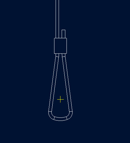
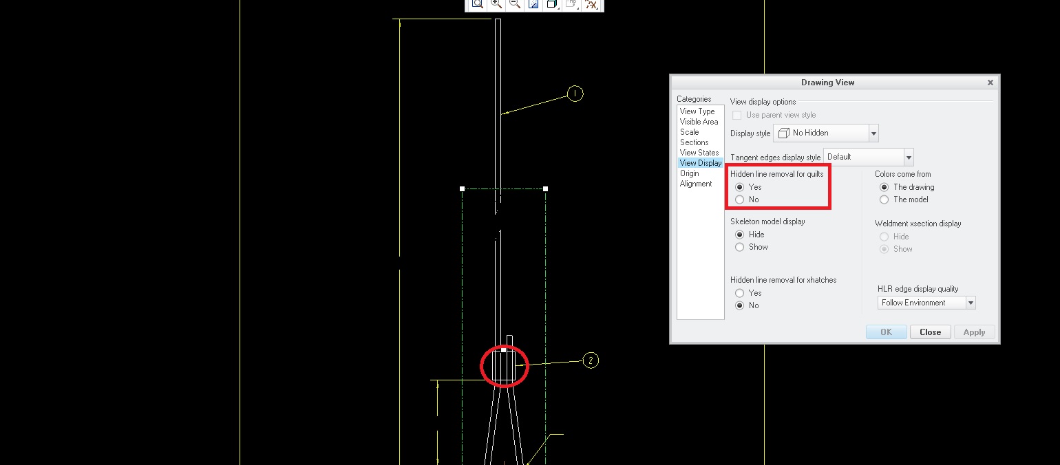
I'm currently working on creating a drawing for an assembly. As you can see in drawing mode, I've selected "No Hidden" as the display style. However, the wire still shows through the sheath in drawing mode (refer to the red circle in the picture below.) I've also attached a picture of the assembly in 3D mode to give an idea of the geometry. As you can see, the clip completely surrounds the wire. How do I prevent the drawing from showing what is inside of the sheath? I am using Creo 2.0.
This thread is inactive and closed by the PTC Community Management Team. If you would like to provide a reply and re-open this thread, please notify the moderator and reference the thread. You may also use "Start a topic" button to ask a new question. Please be sure to include what version of the PTC product you are using so another community member knowledgeable about your version may be able to assist.
Solved! Go to Solution.
Labels:
- Labels:
-
Assembly Design
1 ACCEPTED SOLUTION
Accepted Solutions
Feb 05, 2015
11:39 AM
- Mark as New
- Bookmark
- Subscribe
- Mute
- Subscribe to RSS Feed
- Permalink
- Notify Moderator
Feb 05, 2015
11:39 AM
Wiliam,
Tried a quick test on file and issue seems to be due to accuracy of part wire__.prt. I set the relative accuracy of part wire__.prt to 0.001 and this corrected the view display.
12 REPLIES 12
Feb 04, 2015
02:49 PM
- Mark as New
- Bookmark
- Subscribe
- Mute
- Subscribe to RSS Feed
- Permalink
- Notify Moderator
Feb 04, 2015
02:49 PM
William,
what kind of geometry is created in your parts, solid or surface ? In case of surface geometry, you can set Hidden line removal for quils to Yes in Drawing View dialog box.
Martin Hanak
Martin Hanák
Feb 04, 2015
03:37 PM
- Mark as New
- Bookmark
- Subscribe
- Mute
- Subscribe to RSS Feed
- Permalink
- Notify Moderator
Feb 04, 2015
03:37 PM
There is probably interference between the two parts, which causes the software to be unable to determine which part blocks the other. Or, as Martin suggested, one or both parts are surfaces, aka quilts, which need to have the drawing mode to Hidden link removal for quilts set to be evaluated for hiding capability.
Feb 04, 2015
04:41 PM
- Mark as New
- Bookmark
- Subscribe
- Mute
- Subscribe to RSS Feed
- Permalink
- Notify Moderator
Feb 04, 2015
04:41 PM
Thanks for the suggestions. I have changed "Hidden line removal for quilts" to "Yes" in the drawing view dialog box, as shown in attached picture. This did not correct the issue. Are there any other suggestions anyone might have? Thanks!
Feb 05, 2015
02:41 AM
- Mark as New
- Bookmark
- Subscribe
- Mute
- Subscribe to RSS Feed
- Permalink
- Notify Moderator
Feb 05, 2015
02:41 AM
William,
please upload the model and drawing, if you can.
Martin Hanak
Martin Hanák
Feb 05, 2015
09:55 AM
- Mark as New
- Bookmark
- Subscribe
- Mute
- Subscribe to RSS Feed
- Permalink
- Notify Moderator
Feb 05, 2015
09:55 AM
Files are attached. Thanks for your help!
Feb 05, 2015
11:39 AM
- Mark as New
- Bookmark
- Subscribe
- Mute
- Subscribe to RSS Feed
- Permalink
- Notify Moderator
Feb 05, 2015
11:39 AM
Wiliam,
Tried a quick test on file and issue seems to be due to accuracy of part wire__.prt. I set the relative accuracy of part wire__.prt to 0.001 and this corrected the view display.
Feb 05, 2015
01:20 PM
- Mark as New
- Bookmark
- Subscribe
- Mute
- Subscribe to RSS Feed
- Permalink
- Notify Moderator
Feb 05, 2015
01:20 PM
Thank you. Could you explain where I go to in order to change the relative accuracy?
Feb 05, 2015
01:45 PM
- Mark as New
- Bookmark
- Subscribe
- Mute
- Subscribe to RSS Feed
- Permalink
- Notify Moderator
Feb 05, 2015
01:45 PM
Open Wire part, File > Prepare > Model properties > Accuracy Change > Set relative value as 0.0001 > Regenerate Model > Open drawing and that will be corrected.
Feb 05, 2015
01:51 PM
- Mark as New
- Bookmark
- Subscribe
- Mute
- Subscribe to RSS Feed
- Permalink
- Notify Moderator
Feb 05, 2015
01:51 PM
Thanks so much for your help! The issue is resolved.
Feb 05, 2015
02:00 PM
- Mark as New
- Bookmark
- Subscribe
- Mute
- Subscribe to RSS Feed
- Permalink
- Notify Moderator
Feb 05, 2015
02:00 PM
Part accuracy affects the interference. Leaving it as Relative accuracy will allow the problem to return if the part size changes. It works by adding significantly to the geometry the computer has to process to get a smooth shape. Making the holes even slightly larger would avoid the problem as well, but without increasing the processing required and without the risk of the interference returning,
Feb 04, 2015
04:45 PM
- Mark as New
- Bookmark
- Subscribe
- Mute
- Subscribe to RSS Feed
- Permalink
- Notify Moderator
Feb 04, 2015
04:45 PM
Also, by interference between the two parts, do you mean that the holes in the sheath might be too small for the wire, causing the material in the sheath to overlap the material in the wire? I drew the sheath in assembly mode and made the holes in the sheath the same diameter as the wire.
Feb 04, 2015
04:58 PM
- Mark as New
- Bookmark
- Subscribe
- Mute
- Subscribe to RSS Feed
- Permalink
- Notify Moderator
Feb 04, 2015
04:58 PM
The surfaces and the potential interference are based on the approximations by tesselation. They are not geometrically perfect. You might try measuring clearance between the parts, or just make the holes larger.

.jpg)