
Turn on suggestions
Auto-suggest helps you quickly narrow down your search results by suggesting possible matches as you type.
Showing results for
Turn on suggestions
Auto-suggest helps you quickly narrow down your search results by suggesting possible matches as you type.
Showing results for
Community Tip - New to the community? Learn how to post a question and get help from PTC and industry experts! X
- Community
- Creo+ and Creo Parametric
- 3D Part & Assembly Design
- Closing a gap - default sheetmetal bend radius ope...
Options
- Subscribe to RSS Feed
- Mark Topic as New
- Mark Topic as Read
- Float this Topic for Current User
- Bookmark
- Subscribe
- Mute
- Printer Friendly Page
Closing a gap - default sheetmetal bend radius opening
Jul 28, 2014
04:54 PM
- Mark as New
- Bookmark
- Subscribe
- Mute
- Subscribe to RSS Feed
- Permalink
- Notify Moderator
Jul 28, 2014
04:54 PM
Closing a gap - default sheetmetal bend radius opening
Hi All,
can't figure this out..
I have a sheet metal tub, and the welder is complaining. I don't blame him, I am too!
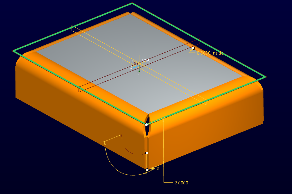
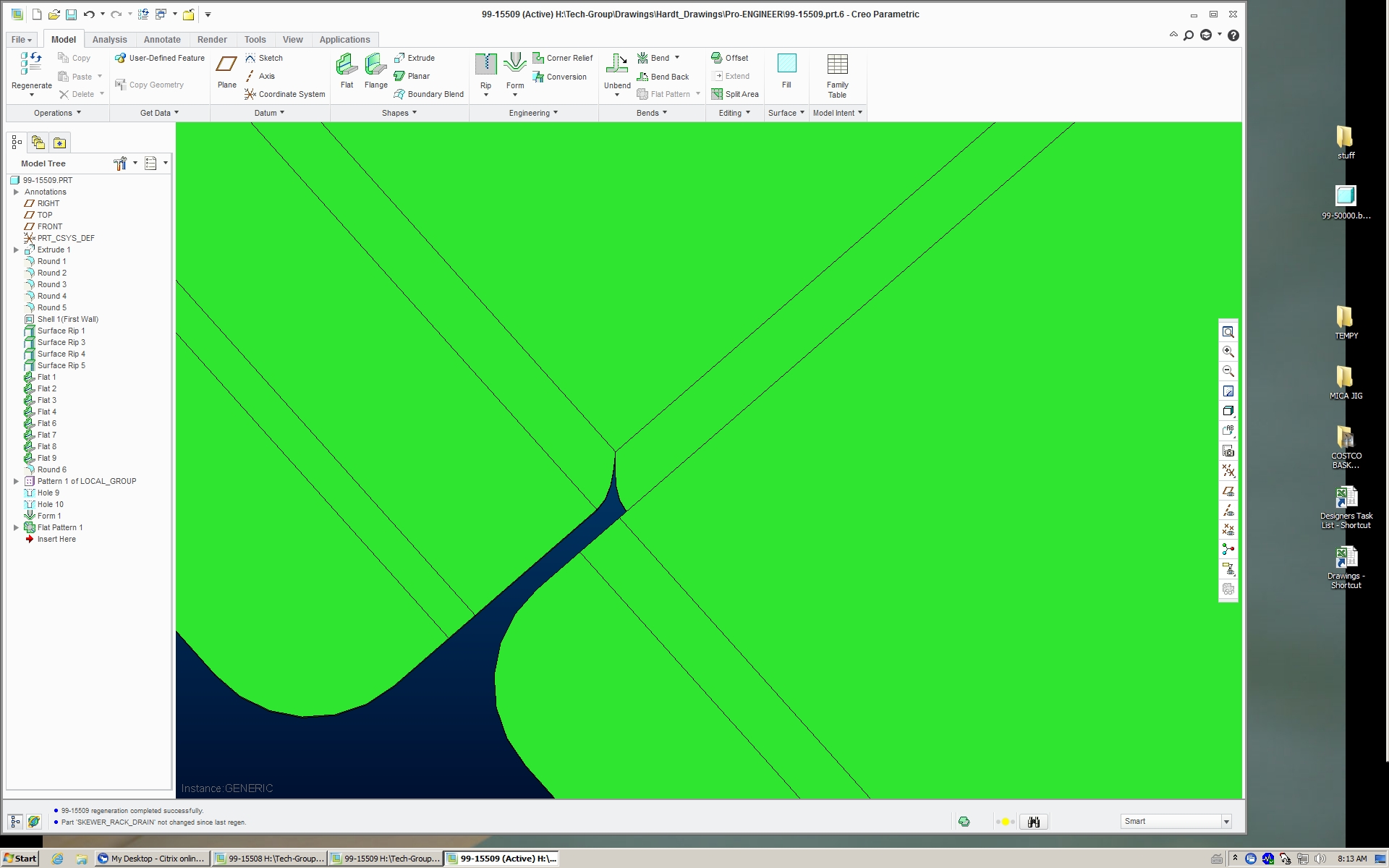
I have a tub, with 4 folded up sides. The bend radius is nice & big, 1/4" radius, for cleanliness & wipe down regulations. But, since this is a bend radius, Creo applies the default bend calc to it, and I get a great opening where the two flanges radius to their vertical, upright positions. I need to add a chord flange, a little arc of material to the ends of the flange where radius is.
I can't seem to add a flange, then cut away want i don't want, because it cuts into the mating flange! I don't know how to add a bit to this flange, and a bit to the other flange, withough cuttting into each other. (I seem to have to 'unbend' then add a flange, then cut away the squareness, to leave my 'chord' portion.. But that cuts into the other side, so i can only modify one side, while mutilating the other..) And the 'extend' don't work, cuse I'm grabbing the teh same face edge in Creo's eyes.. Or something. (Extend never worked for us in Creo 2, or is very tempremental.. bug?!)
Any ideas on how to close this off? (Without pulling the 2D flat pattern into Acad & doing it there?)
see attached for the gap / hole I'm trying to close
thanks,
Paul
Add this to the Sheet Metal gripes: not being able to draw a flange the shape you want without first having to establish a 'basic' flange first & cuttting it from that..
This thread is inactive and closed by the PTC Community Management Team. If you would like to provide a reply and re-open this thread, please notify the moderator and reference the thread. You may also use "Start a topic" button to ask a new question. Please be sure to include what version of the PTC product you are using so another community member knowledgeable about your version may be able to assist.
Solved! Go to Solution.
Labels:
- Labels:
-
Assembly Design
1 ACCEPTED SOLUTION
Accepted Solutions
Jul 28, 2014
05:00 PM
- Mark as New
- Bookmark
- Subscribe
- Mute
- Subscribe to RSS Feed
- Permalink
- Notify Moderator
Jul 28, 2014
05:00 PM
Add your large corner radii prior to the shell and then, also prior to the shell, add a round to the edge where the joint would be that's 2X 1X the wall thickness. Nowm,after the shell use a surface rip to remove the 1X radius round surfaces.
17 REPLIES 17
Jul 28, 2014
05:00 PM
- Mark as New
- Bookmark
- Subscribe
- Mute
- Subscribe to RSS Feed
- Permalink
- Notify Moderator
Jul 28, 2014
05:00 PM
Add your large corner radii prior to the shell and then, also prior to the shell, add a round to the edge where the joint would be that's 2X 1X the wall thickness. Nowm,after the shell use a surface rip to remove the 1X radius round surfaces.
Jul 28, 2014
05:36 PM
- Mark as New
- Bookmark
- Subscribe
- Mute
- Subscribe to RSS Feed
- Permalink
- Notify Moderator
Jul 28, 2014
05:36 PM
You are on the right track, Paul. You do want the flange, but you want to add the flange to both edges (or all 4). This will create the v-notch you are wanting.
You can even add some overlap if your welder wants additional material (edge treatment).
Jul 29, 2014
10:07 AM
- Mark as New
- Bookmark
- Subscribe
- Mute
- Subscribe to RSS Feed
- Permalink
- Notify Moderator
Jul 29, 2014
10:07 AM
Thanks guys,
But..
Doug, doing so, or as i understand it, removes the 2*mat thickness radius previously added [adding a surface rip]. Therefore, my edges don't meet, and the gap, although smaller is still there. Then, I have the added difficulty of trying to get my vertical edges to meet, as per normal. I can extend the edges, but I cannot extend less than the bend radii: 1/4" in this case. I can, however, extend both edges the 1/4" min Creo allows, but then I have two intersecting flanges..
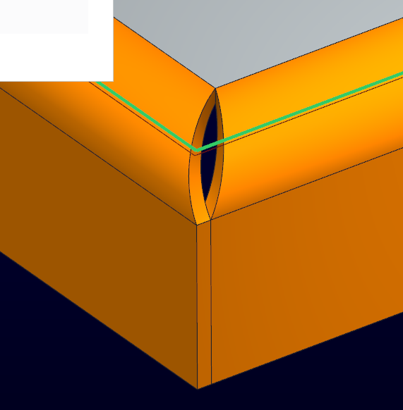
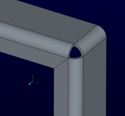
Now, if I do a surface rip, and remove one entire side (bend & flange) I get want I want, but on one flange, and now I need to make a new flange to match... I can add a new flange, but it gives the standard, straight 'V' edge, and the opening is one sided, and still can't be closed... (See pic at bottom: left edge as I want, the right edge per Creo)
Antonius, that is what I'm getting, but i still have that huge opening that needs to be welded closed. I'm not after a 'V' notch with straight sides, but more of a curvy 'V' notch; each straight side of the 'V' should be a curve...
And my vertical edges should be as per normal, each inside edge mating, as per the original pic attached..
The welder wants to just run a bead , a filet, on the two mating edges, not plug a 1/8" opening..
this pic show one edge of my flat, as i expect my notch to look like. but to do two, mating flanges like this...
Jul 29, 2014
10:16 AM
- Mark as New
- Bookmark
- Subscribe
- Mute
- Subscribe to RSS Feed
- Permalink
- Notify Moderator
Jul 29, 2014
10:16 AM
Doung, you got it!!
You mentined 2x material thickness, that leaves a gap. But, dogin 1x material thinkness seesm to be it!!
Jul 29, 2014
11:31 AM
- Mark as New
- Bookmark
- Subscribe
- Mute
- Subscribe to RSS Feed
- Permalink
- Notify Moderator
Jul 29, 2014
11:31 AM
Sorry about that, I meant 1X. I corrected my post above for clarity. 😛
Glad I could help. Please mark the correct answer, it'll help folks in the future.
Jul 30, 2014
12:57 AM
- Mark as New
- Bookmark
- Subscribe
- Mute
- Subscribe to RSS Feed
- Permalink
- Notify Moderator
Jul 30, 2014
12:57 AM
Can you post a file with the desired results?
Jul 30, 2014
10:14 AM
- Mark as New
- Bookmark
- Subscribe
- Mute
- Subscribe to RSS Feed
- Permalink
- Notify Moderator
Jul 30, 2014
10:14 AM
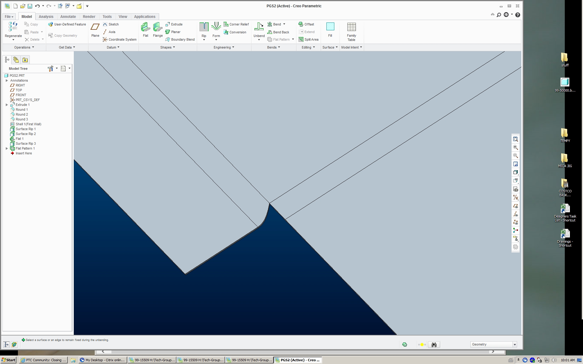
Results as requested:
this is teh inteded corner, closed with the inner edges meetign, so that a fillet weld can be added to teh two faces. No need to plug / fill in a huge hole.
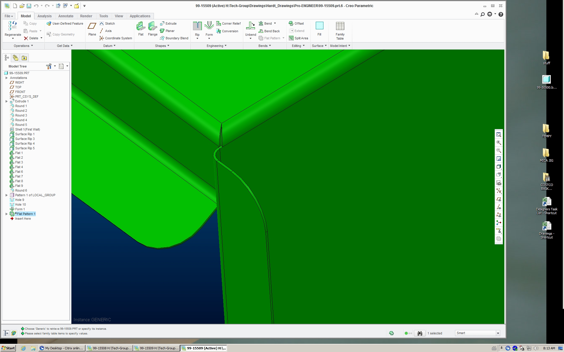
What the flat pattern looks like. You can see the 'V' notch is not straight, but curved edges.
Jul 30, 2014
01:10 PM
- Mark as New
- Bookmark
- Subscribe
- Mute
- Subscribe to RSS Feed
- Permalink
- Notify Moderator
Jul 30, 2014
01:10 PM
What is the orientation of the surface rip? I always have a lot of trouble getting rips to work right.
Jul 30, 2014
01:30 PM
- Mark as New
- Bookmark
- Subscribe
- Mute
- Subscribe to RSS Feed
- Permalink
- Notify Moderator
Jul 30, 2014
01:30 PM
A surface rip really has no orientation. You simply select a surface to "rip" away (remove), in this case a round.
Jul 30, 2014
07:27 PM
- Mark as New
- Bookmark
- Subscribe
- Mute
- Subscribe to RSS Feed
- Permalink
- Notify Moderator
Jul 30, 2014
07:27 PM
I'm not getting there. I can remove the round surface, but it removes the entire surface. Then I cannot get it to make the other wall (which is the topic of discussion, obviously).
Can someone please post a file to I can interrogate?
Jul 30, 2014
07:55 PM
- Mark as New
- Bookmark
- Subscribe
- Mute
- Subscribe to RSS Feed
- Permalink
- Notify Moderator
Jul 30, 2014
07:55 PM
Duh! Never mind. Now I got it.
So you cannot do this in native sheetmetal (?) !
Jul 31, 2014
08:53 AM
- Mark as New
- Bookmark
- Subscribe
- Mute
- Subscribe to RSS Feed
- Permalink
- Notify Moderator
Jul 31, 2014
08:53 AM
Check out this part. It was created in WF4, should show you what you need to know.
Jul 31, 2014
09:17 AM
- Mark as New
- Bookmark
- Subscribe
- Mute
- Subscribe to RSS Feed
- Permalink
- Notify Moderator
Jul 31, 2014
09:17 AM
Yes, I re-read your original reply and finally got the trick.
But you have to start in solid modeling and convert it to sheetmetal.
No way to do this from scratch inside a sheetmetal part?
Jul 31, 2014
03:22 PM
- Mark as New
- Bookmark
- Subscribe
- Mute
- Subscribe to RSS Feed
- Permalink
- Notify Moderator
Jul 31, 2014
03:22 PM
Yeah, that's what burned me. The start of my part was a flat plate. I had to redraw the whole part, starting with a solid. Once that was rebuilt, I then had to re-assembled it all back into the assemblies I had. lost 2 days in total..
Jul 31, 2014
03:39 PM
- Mark as New
- Bookmark
- Subscribe
- Mute
- Subscribe to RSS Feed
- Permalink
- Notify Moderator
Jul 31, 2014
03:39 PM
But! ... how many mouse clicks did you save? 
Aug 01, 2014
01:03 PM
- Mark as New
- Bookmark
- Subscribe
- Mute
- Subscribe to RSS Feed
- Permalink
- Notify Moderator
Aug 01, 2014
01:03 PM
haha, saving mouse clicks... At least i had drawings to work from!!
Actaully, the number of mouse clicks dosen't (really) get to me, it's the @#$%^ constant use of the middle button all the time!! I remeber having 3 button on my mouse back in .. '94? 95?, but since 2001, the middle button has traditionally been a wheel, with little expected 'clicking' use! scrolling yes, clicking no. Why does PTC hold onto this?!
Aug 01, 2014
01:17 PM
- Mark as New
- Bookmark
- Subscribe
- Mute
- Subscribe to RSS Feed
- Permalink
- Notify Moderator
Aug 01, 2014
01:17 PM
When I went back to Pro|E after years of NX, I had a 3-button mouse and somehow from the years of mothballs, the solder joint on the middle button cracked and oxidized. Drove me nuts when I tried dropping a dimension in sketcher and it wouldn't do it! So I know where you are coming from.
Still looking for a trick to minimize this joint...
Vote here: Sheetmetal - true "min bend relief" feature
