
Turn on suggestions
Auto-suggest helps you quickly narrow down your search results by suggesting possible matches as you type.
Showing results for
Turn on suggestions
Auto-suggest helps you quickly narrow down your search results by suggesting possible matches as you type.
Showing results for
Community Tip - Want the oppurtunity to discuss enhancements to PTC products? Join a working group! X
- Community
- Creo+ and Creo Parametric
- 3D Part & Assembly Design
- Re: Constrain equal angles
Options
- Subscribe to RSS Feed
- Mark Topic as New
- Mark Topic as Read
- Float this Topic for Current User
- Bookmark
- Subscribe
- Mute
- Printer Friendly Page
Constrain equal angles
Nov 06, 2018
05:01 AM
- Mark as New
- Bookmark
- Subscribe
- Mute
- Subscribe to RSS Feed
- Permalink
- Notify Moderator
Nov 06, 2018
05:01 AM
Constrain equal angles
Hello everybody,
I have been working with ProEngineer/Creo for almost 4 years already. Of course, I had to check many times the discussions in that community, always finding a solution to my issues and being able to handle them.
But I could not find an answer to today´s problem yet... See below explanations regarding the issue, as well as my main worklines.
________________________________________________________________________
The model I want to create can be simplified considering it as two joints in a row, but imposing some constrains to their angles.
As you can see in the pictures below, turning angles of red crosses must be equal all the time. In the same way, turning angles of yellow hitches must be equal as well.
[PHOTO_1.jpg]
I want to implement that constrains so that I can include the component in a driveline and perform kinematic analysis on it.
I tried to do it in two different ways:
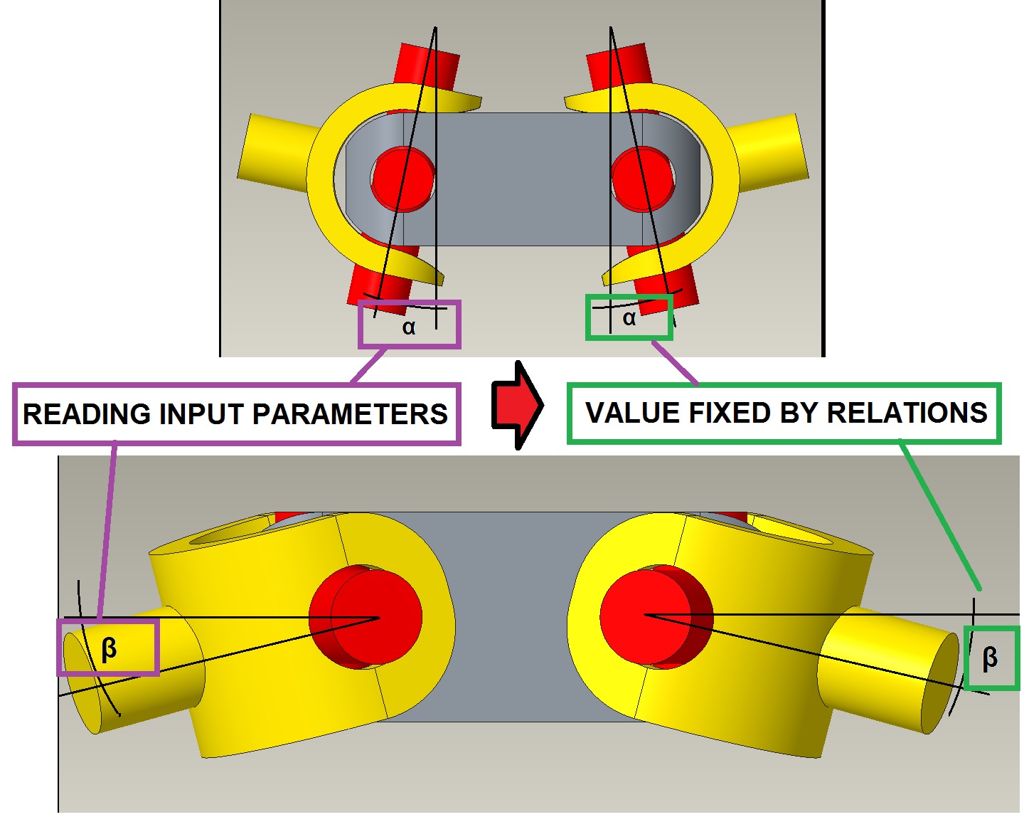
1. I created two input parameters, reading "alfa" and "beta" in the first joke. Then, I created a relationship stating that "alfa" and "beta" in the second joke are equal to the input parameters values.
[PHOTO_2.jpg]
This way gives me two problems. The first one is that just the input angles are free when I drag the components, and the output ones are chosen once I regenerate the model.
Not only that, every time I regenerate, the "reading input parameters" change. So, I need to regenerate many times until output and input parameters are more or less equal...
That method is not either smart or accurate, and I think I could do it better.
2. I used the constrain "Gears"
It worked fine in order to constrain the two red corsses, and it looks exactly what I wanted to get. See constrain details attached.
[PHOTO_3.jpg]
But the problem came up when I constrained the yellow hitches. It worked, but the I lost the first constrain, the one constraining the red crosses... and I cannot move them anymore.
[PHOTO_4.jpg]
Can anybody give me some advice of how to successfully constrain my model? I am striggling a lot without getting any improvement!
Thanks a lot in advance!
BR
C.Reoyo
Solved! Go to Solution.
Labels:
- Labels:
-
Design Exploration
1 ACCEPTED SOLUTION
Accepted Solutions
Nov 07, 2018
08:07 AM
- Mark as New
- Bookmark
- Subscribe
- Mute
- Subscribe to RSS Feed
- Permalink
- Notify Moderator
Nov 07, 2018
08:07 AM
Hi Doug,
Finally I could solve my issue! It was not easy, and the final solution was really far from my attemps aim... But I got it!
So, I will leave here the explanation in case someone needs it in the future.
The real component I wanted to model is a Constant Velocity (CV) joint. Confidentiality wise, I did not want to show the real 3D model.
In order to get the desider result I added an extra component, which needs to be no more that a point and a plane containing that point. In the pictures I also drew a transparent sphere to make the point visible.

In order to fulfil the conditions requested in the first post, the axis of the input and output shafts must match always in a point contained in the middle plane of the grey bracket.
In order to get that, I constrained the new component (orange sphere) using 3 different set of constrains:
1. Bearing constrain forcing the ficticious point to be located along the input shaft axis.
2. Bearing constrain forcing the ficticious point to be located along the output shaft axis.
3. Planar constrain forcing the ficticious point to belong to the grey frame middleplane.

Now, the goal constrains regarding angles are reached in both the current assembly and bigger ones.
P.S: Anyhow, thanks a lot for your support Doug!!
C.Reoyo
2 REPLIES 2
Nov 06, 2018
08:25 AM
- Mark as New
- Bookmark
- Subscribe
- Mute
- Subscribe to RSS Feed
- Permalink
- Notify Moderator
Nov 06, 2018
08:25 AM
Consider a physical version of this mechanism. By itself, there is nothing to constrain the angles to be equal, each side is free to move independently. Only when the pins of the yellow parts are assembled to input and output shafts of the larger assembly is it forced to be equal.
My thought is that you create the pin constraints as you have, perhaps with angle limits, and then assemble it in the larger assy, using pin constraints on the input and output shafts. Then, as in the physical assy, the equal angles may take care of themselves.
Nov 07, 2018
08:07 AM
- Mark as New
- Bookmark
- Subscribe
- Mute
- Subscribe to RSS Feed
- Permalink
- Notify Moderator
Nov 07, 2018
08:07 AM
Hi Doug,
Finally I could solve my issue! It was not easy, and the final solution was really far from my attemps aim... But I got it!
So, I will leave here the explanation in case someone needs it in the future.
The real component I wanted to model is a Constant Velocity (CV) joint. Confidentiality wise, I did not want to show the real 3D model.
In order to get the desider result I added an extra component, which needs to be no more that a point and a plane containing that point. In the pictures I also drew a transparent sphere to make the point visible.
In order to fulfil the conditions requested in the first post, the axis of the input and output shafts must match always in a point contained in the middle plane of the grey bracket.
In order to get that, I constrained the new component (orange sphere) using 3 different set of constrains:
1. Bearing constrain forcing the ficticious point to be located along the input shaft axis.
2. Bearing constrain forcing the ficticious point to be located along the output shaft axis.
3. Planar constrain forcing the ficticious point to belong to the grey frame middleplane.
Now, the goal constrains regarding angles are reached in both the current assembly and bigger ones.
P.S: Anyhow, thanks a lot for your support Doug!!
C.Reoyo
