
Turn on suggestions
Auto-suggest helps you quickly narrow down your search results by suggesting possible matches as you type.
Showing results for
Turn on suggestions
Auto-suggest helps you quickly narrow down your search results by suggesting possible matches as you type.
Showing results for
- Community
- Creo+ and Creo Parametric
- 3D Part & Assembly Design
- Re: Failing Connections in an Assembly
Options
- Subscribe to RSS Feed
- Mark Topic as New
- Mark Topic as Read
- Float this Topic for Current User
- Bookmark
- Subscribe
- Mute
- Printer Friendly Page
Failing Connections in an Assembly
Mar 24, 2011
03:04 PM
- Mark as New
- Bookmark
- Subscribe
- Mute
- Subscribe to RSS Feed
- Permalink
- Notify Moderator
Mar 24, 2011
03:04 PM
Failing Connections in an Assembly
Greetings, all! I'm kinda new around here, but not new to Pro/E...although some days it feels that way! Anyhow, I have an issue where I am assembling a conceptual solenoid-linkage using connections. However, they are failing to some extent. Here's the description of what's going on in the picture: The pink gear is assembled to the shaft using Cylinder. It moves axially 22.225mm and rotates 360 degrees freely. The blue trunnion collar is assembled to the pink gear using Cylinder and moves along with it. It is also Aligned to the centerline and Aligned from its bottom surface to the top surface of the pink gear. Next, the green bar is assembled using Cylinder at the fulcrum, and then to the blue trunnion collar using the Slot connection. With these assembled, I can hold down Ctrl+Alt and pick the green bar with the L Mouse Btn, and the linkages and gear will move up and down like I want it to. Now, when I assemble (or attempt to assemble) the solenoid plunger to the other slotted end of the green bar, the whole assembly fails to move as it should. Seems like the connections are fighting each other and it's frozen. I've tried every combo for the other slot: Bearing, Slot, etc. to no avail. Any suggestions? Let me know if you need more details...for the record I'm using Wildfire 4. Thanks and best regards, Edward
This thread is inactive and closed by the PTC Community Management Team. If you would like to provide a reply and re-open this thread, please notify the moderator and reference the thread. You may also use "Start a topic" button to ask a new question. Please be sure to include what version of the PTC product you are using so another community member knowledgeable about your version may be able to assist.
Labels:
- Labels:
-
Assembly Design
9 REPLIES 9
Mar 25, 2011
07:40 AM
- Mark as New
- Bookmark
- Subscribe
- Mute
- Subscribe to RSS Feed
- Permalink
- Notify Moderator
Mar 25, 2011
07:40 AM
Do you want the plunger to control the movement? If the blue piece is assembled using cylinder & is constrained as you say then you can grab the green bar & move within your limits. I would use a pin constraint to connect the green bar to your plunger. I am assuming that your plunger is a two part assembly with a cylinder connection to control the movement of it. With the failure you're describing it sounds like there is a conflict with your cylinder constraints.
Mar 28, 2011
03:12 PM
- Mark as New
- Bookmark
- Subscribe
- Mute
- Subscribe to RSS Feed
- Permalink
- Notify Moderator
Mar 28, 2011
03:12 PM
Mike,
Yes, the plunger shall control the movement of the linkage assembly. I've tried connectiing to it using Pin, but it still fails.
For the record, I've also tried changing the green bar's fulcrum to Pin, but this also fails.
I appreciate any other insights you may have...thanks for the help.
Ed
Mar 28, 2011
03:26 PM
- Mark as New
- Bookmark
- Subscribe
- Mute
- Subscribe to RSS Feed
- Permalink
- Notify Moderator
Mar 28, 2011
03:26 PM
I would start by assemblying the plunger to the green bar first & get that working. then add your connections & eliminate the problem. I have had many problems like this before you just have to go back through it. Let me know if you are still having problems & I can look more at it tomorrow./
Mar 29, 2011
01:27 PM
- Mark as New
- Bookmark
- Subscribe
- Mute
- Subscribe to RSS Feed
- Permalink
- Notify Moderator
Mar 29, 2011
01:27 PM
I've done this experiment: assembled the plunger to the green bar using Slot, and assembled the green bar to the trunnion collar, also using Slot.
I also Disabled the Cylinder in the fulcrum, just to see the behavior of the system. Both slots work fine, sliding the point on the datum curve (a short, straight line from axis to axis in each the green bar's slots). However, the green bar is free to rotate lengthwise now, not being held in place at the fulcrum. But as soon as I enable Cylinder, or change it to Pin, the whole system locks up. Or rather, it will make the first "stroke", then freeze.
Hope my descriptions make sense? What other potential Connections could the fulcrum be?
Thanks,
Ed
Mar 29, 2011
03:23 PM
- Mark as New
- Bookmark
- Subscribe
- Mute
- Subscribe to RSS Feed
- Permalink
- Notify Moderator
Mar 29, 2011
03:23 PM
So the green bar is assembled with three pin connections right? When you move the mechanism the collar moves also right? Then when you add the cylinder contraint it locks up right? It doesn't like the pin connection & cylinder connection. It is soomething to do wiht your connections. I will try an example tomorrow & let you know.
Mar 29, 2011
04:08 PM
- Mark as New
- Bookmark
- Subscribe
- Mute
- Subscribe to RSS Feed
- Permalink
- Notify Moderator
Mar 29, 2011
04:08 PM
Here's my order of assembling components:
First, the gear is assembled using Cylinder, and it's free to rotate 360 degrees and slide up & down axially approx. 20mm. Then, the blue collar is assembled to the gear using Cylinder, and two General connections, one to offset it from the bottom face of the gear, the other to align it to the centerline of the plunger and green bar. It is fixed to the gear when it moves axially, but allows the gear to rotate its 360 degrees as previously described. Next, the solenoid is asembled, then the plunger to it, using Cylinder and a 14mm stroke. Finally, the green bar is assembled using Cylinder in the middle hole, and a Slot for both connections to the collar and and the plunger. I've re-attached a JPG of my system showing it in detail.
Ed
Mar 30, 2011
09:47 AM
- Mark as New
- Bookmark
- Subscribe
- Mute
- Subscribe to RSS Feed
- Permalink
- Notify Moderator
Mar 30, 2011
09:47 AM
I have made a similar mechanism & was able to get the same failure as you. You can look at the attached picture below. You have to allow for some play in one of your connections. You cant have both pin connections. When the movement happens the distance from the holes change so you have to use a slot connection. You just need to widen one of your holes & put a sketch in there. Then create a point in the connection hole for the body part. Then you can use the point & sketch to make the slot connection. then as you move the plunger the bar follows the line you have specified. I dont think it would matter which one you put the slot connection on. I hope this helps.
Mar 30, 2011
02:15 PM
- Mark as New
- Bookmark
- Subscribe
- Mute
- Subscribe to RSS Feed
- Permalink
- Notify Moderator
Mar 30, 2011
02:15 PM
To close out this thread, unless someone has something else to add to it...a big thanks for your help, Mike.
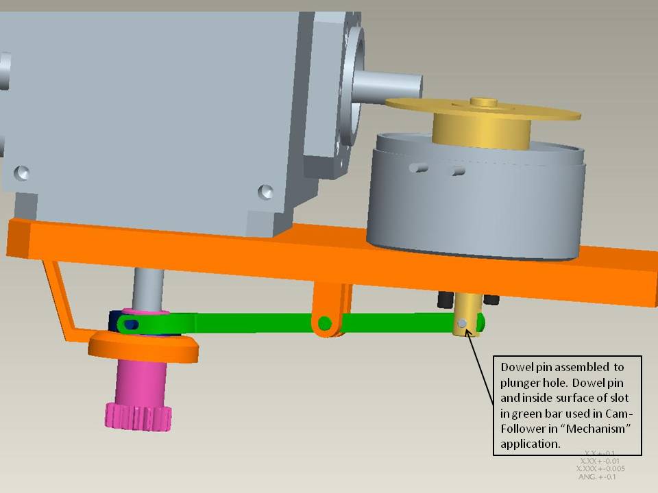
This is what I did to finally get the system to work. At the plunger, I assembled a dowel pin and then assembled it to the green bar in Mechanism, using the Cam-Follower Connection. The OD of the dowel pin (Cam 1) and the inner surface of the slot (Cam 2) on the green bar are now functional.
The nice thing about this is that even when you exit the Mechanical application, the system will work if you use the Drag Component to move it.
I've uploaded a JPG to show the system successfully assembled and now working.
Regards,
Edward
Mar 30, 2011
02:28 PM
- Mark as New
- Bookmark
- Subscribe
- Mute
- Subscribe to RSS Feed
- Permalink
- Notify Moderator
Mar 30, 2011
02:28 PM
No problem. I am glad it is working for you now.
