
Turn on suggestions
Auto-suggest helps you quickly narrow down your search results by suggesting possible matches as you type.
Showing results for
Turn on suggestions
Auto-suggest helps you quickly narrow down your search results by suggesting possible matches as you type.
Showing results for
Community Tip - You can subscribe to a forum, label or individual post and receive email notifications when someone posts a new topic or reply. Learn more! X
- Community
- Creo+ and Creo Parametric
- 3D Part & Assembly Design
- Fasteners: "cannot pair the linked assembly elemen...
Options
- Subscribe to RSS Feed
- Mark Topic as New
- Mark Topic as Read
- Float this Topic for Current User
- Bookmark
- Subscribe
- Mute
- Printer Friendly Page
Fasteners: "cannot pair the linked assembly elements"
Jun 01, 2016
12:25 PM
- Mark as New
- Bookmark
- Subscribe
- Mute
- Subscribe to RSS Feed
- Permalink
- Notify Moderator
Jun 01, 2016
12:25 PM
Fasteners: "cannot pair the linked assembly elements"
I'm having another try at using fasteners, but like most things in Creo it's pretty tricky without a training course or an expert on hand.
The diagnostics during meshing are returning the fatal error "Creo Simulate cannot pair the linked assembly elements near the highlighted entities. Try modifying the geometry to correct the problem." It meshes fine with the fasteners suppressed.
Here's one of the offending fasteners, with its details:

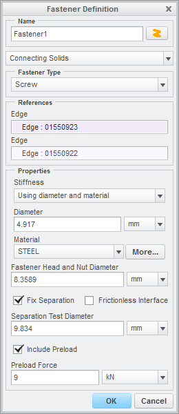
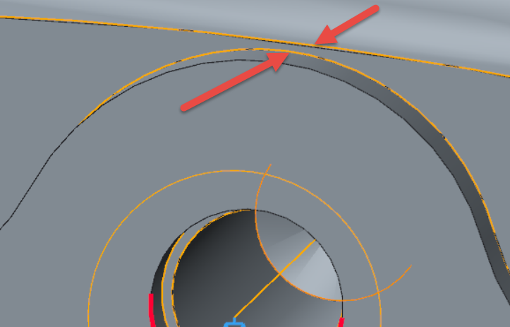
The surface highlighted to go with the error message is the face of the rear component, that the flange is clamped up against.
What's even more frustrating is that I had it working with just a couple of fasteners, so I added the rest; it then stopped working, so I tried a few things, then went back to just a couple, and now it still doesn't work!
Could someone give me some pointers on how I should be using fasteners in this situation, please? What is the mesher trying to do due to the fastener that causes it to fail?
Solved! Go to Solution.
Labels:
- Labels:
-
Assembly Design
1 ACCEPTED SOLUTION
Accepted Solutions
Jun 02, 2016
05:19 AM
- Mark as New
- Bookmark
- Subscribe
- Mute
- Subscribe to RSS Feed
- Permalink
- Notify Moderator
Jun 02, 2016
05:19 AM
Thanks Don! It wasn't quite that - I tried reducing the separation diameter, and I tried adding a cut to avoid that narrow gap at the top of the flange; but eventually I tried increasing the separation diameter (to 11) and that worked.
4 REPLIES 4
Jun 01, 2016
07:06 PM
- Mark as New
- Bookmark
- Subscribe
- Mute
- Subscribe to RSS Feed
- Permalink
- Notify Moderator
Jun 01, 2016
07:06 PM
Hi Jonathan,
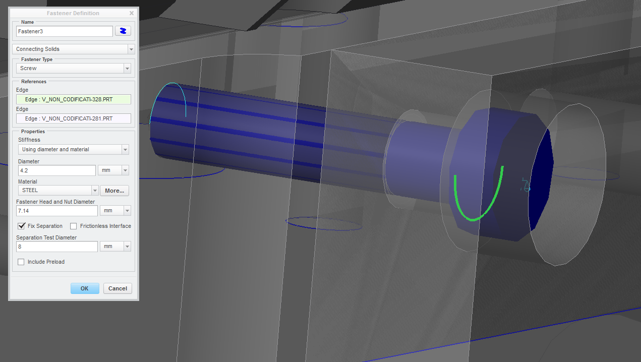
It might be having trouble with the fixed separation related to the location of the tangency of the rounded tab on the plate that's being fastened to the base part that has an Edge Round. You might try reducing the separation diameter.
Have you checked the simulation fastener diameter to make sure it's the same size as the minor diameter of the tapped hole or smaller?
Hope this helps,
Don Anderson
Jun 02, 2016
05:19 AM
- Mark as New
- Bookmark
- Subscribe
- Mute
- Subscribe to RSS Feed
- Permalink
- Notify Moderator
Jun 02, 2016
05:19 AM
Thanks Don! It wasn't quite that - I tried reducing the separation diameter, and I tried adding a cut to avoid that narrow gap at the top of the flange; but eventually I tried increasing the separation diameter (to 11) and that worked.
Jun 03, 2016
08:15 AM
- Mark as New
- Bookmark
- Subscribe
- Mute
- Subscribe to RSS Feed
- Permalink
- Notify Moderator
Jun 03, 2016
08:15 AM
Aaargh! Here I am, staying a little longer to try to launch a sensitivity study on some geometry that isn't really near the fasteners, and the problem's come back! Now I have to guess at new values, update a dozen fasteners, then let it try meshing again and wait for ages to see whether it's going to fail.
Not only that, but in the summary file it just comes up as a "requested shape change failed - internal engine error has occurred". You have to have Diagnostics running to see the actual error. Stupid software...
May 27, 2017
02:46 AM
- Mark as New
- Bookmark
- Subscribe
- Mute
- Subscribe to RSS Feed
- Permalink
- Notify Moderator
May 27, 2017
02:46 AM
Hello!
I have the same problem
i I increase or decrease test diameter value (min.l 8 value), the mesh comand don't run with the same messagge in object
Maybe the problem is this?
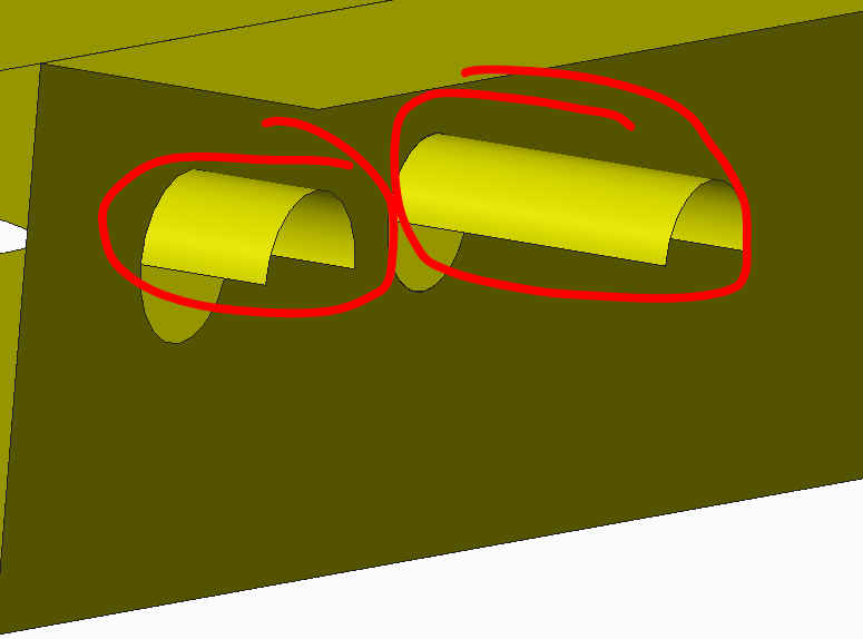
With the command "Review Geometry", There are these surface... I think that is incorrect.
