
Turn on suggestions
Auto-suggest helps you quickly narrow down your search results by suggesting possible matches as you type.
Showing results for
Turn on suggestions
Auto-suggest helps you quickly narrow down your search results by suggesting possible matches as you type.
Showing results for
Community Tip - You can change your system assigned username to something more personal in your community settings. X
- Community
- Creo+ and Creo Parametric
- 3D Part & Assembly Design
- Re: Functional Door Assembly
Options
- Subscribe to RSS Feed
- Mark Topic as New
- Mark Topic as Read
- Float this Topic for Current User
- Bookmark
- Subscribe
- Mute
- Printer Friendly Page
Functional Door Assembly
Aug 05, 2019
02:56 PM
- Mark as New
- Bookmark
- Subscribe
- Mute
- Subscribe to RSS Feed
- Permalink
- Notify Moderator
Aug 05, 2019
02:56 PM
Functional Door Assembly
I'm attempting to assemble an electrical box. I've got the enclosure, a 2-part bullet hinge, and the door. I currently have the bottom half of the bullet hinge fixed to the enclosure, and the upper half setup with a pin constraint so that it can rotate. I attempting to connect the door panel to the upper hinge half, but as soon as I did this, neither the hinge nor the door panel could rotate on the lower hinge. Is it possible to constrain the door panel such that it will move with the upper portion of the hinge when I use "Drag Components"?

Solved! Go to Solution.
Labels:
- Labels:
-
Assembly Design
1 ACCEPTED SOLUTION
Accepted Solutions
Aug 05, 2019
04:04 PM
- Mark as New
- Bookmark
- Subscribe
- Mute
- Subscribe to RSS Feed
- Permalink
- Notify Moderator
Aug 05, 2019
04:04 PM
Why don't you connect the upper hinge to the door panel. Then connect the door assembly to the box assembly?
Align the axis of one of the hinges, coincident for the face of the upper and lower half of the hinge, then angle offset of the door with respect to the cabinet?
3 REPLIES 3
Aug 05, 2019
04:04 PM
- Mark as New
- Bookmark
- Subscribe
- Mute
- Subscribe to RSS Feed
- Permalink
- Notify Moderator
Aug 05, 2019
04:04 PM
Why don't you connect the upper hinge to the door panel. Then connect the door assembly to the box assembly?
Align the axis of one of the hinges, coincident for the face of the upper and lower half of the hinge, then angle offset of the door with respect to the cabinet?
Aug 07, 2019
08:31 AM
- Mark as New
- Bookmark
- Subscribe
- Mute
- Subscribe to RSS Feed
- Permalink
- Notify Moderator
Aug 07, 2019
08:31 AM
Mechanism requires careful assembly of components. The most common error that I have seen is constraining a part to multiple parts. This applies to the part in mechanism and any part attached to that part. Another other common issue is allowing assumptions to parts on the part in mechanism.
Looking at your assembly, I would suggest that you ensure the door is assembled to only one hinge leaf.
There is always more to learn in Creo.
Aug 13, 2019
09:57 AM
- Mark as New
- Bookmark
- Subscribe
- Mute
- Subscribe to RSS Feed
- Permalink
- Notify Moderator
Aug 13, 2019
09:57 AM
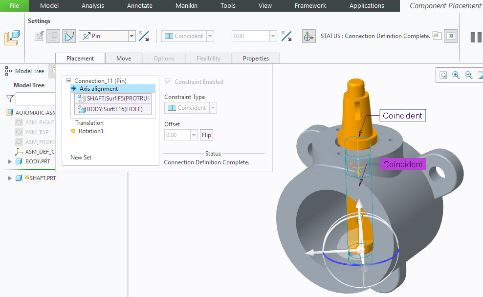
You need to first decide if you are going to constrain the component using constraints or connections. It sounds like you're trying to use connections here. In this case, a single Pin constraint on one of the hinges should suffice to give you the motion that you're looking for. You could select the two axes/cylindrical surfaces on the two components for the rotation axis references, and then select two planar surfaces/datum planes to lock the translation and complete the connection definition. This single Pin constraint will turn the component orange, indicating it is fully constrained. However, the 3D Dragger will still display the rotational degree of freedom as being available, and the component will appear in the model tree with a little open square next to it. Adding a Fix constraint locks all degrees of freedom and will not allow the component to move at all.
Alternatively, you could use Constraints to enable the same motion. However, in this case you cannot fully constrain the component. That is, it must remain purple in the graphics window, also known as "Partially Constrained", or "Packaged". This will show the component in the model tree with a little open square next to it. Essentially, when you see a component in the model tree with the little open square it indicates that there are degrees of freedom still available and you can use Drag Components to move it. For this case you would create a Coincident constraint for the two axes/cylindrical constraints. You would then create another Coincident constraint and select two planar surfaces/datum planes to lock translation. You would then uncheck the option for "Allow Assumptions" in the Placement tab. This would re-enable the rotational degree of freedom around the axis.
You *could* add an additional Angle Offset constraint to control the rotational angle with a dimension. However, this would fully constrain the component and thus not make it available to be dragged using Drag Components.
-------
Matt Huybrecht
Matt Huybrecht
