
Turn on suggestions
Auto-suggest helps you quickly narrow down your search results by suggesting possible matches as you type.
Showing results for
Turn on suggestions
Auto-suggest helps you quickly narrow down your search results by suggesting possible matches as you type.
Showing results for
Community Tip - Have a PTC product question you need answered fast? Chances are someone has asked it before. Learn about the community search. X
- Community
- Creo+ and Creo Parametric
- 3D Part & Assembly Design
- Help! sanity check needed
Options
- Subscribe to RSS Feed
- Mark Topic as New
- Mark Topic as Read
- Float this Topic for Current User
- Bookmark
- Subscribe
- Mute
- Printer Friendly Page
Help! sanity check needed
Jul 28, 2015
12:20 PM
- Mark as New
- Bookmark
- Subscribe
- Mute
- Subscribe to RSS Feed
- Permalink
- Notify Moderator
Jul 28, 2015
12:20 PM
Help! sanity check needed
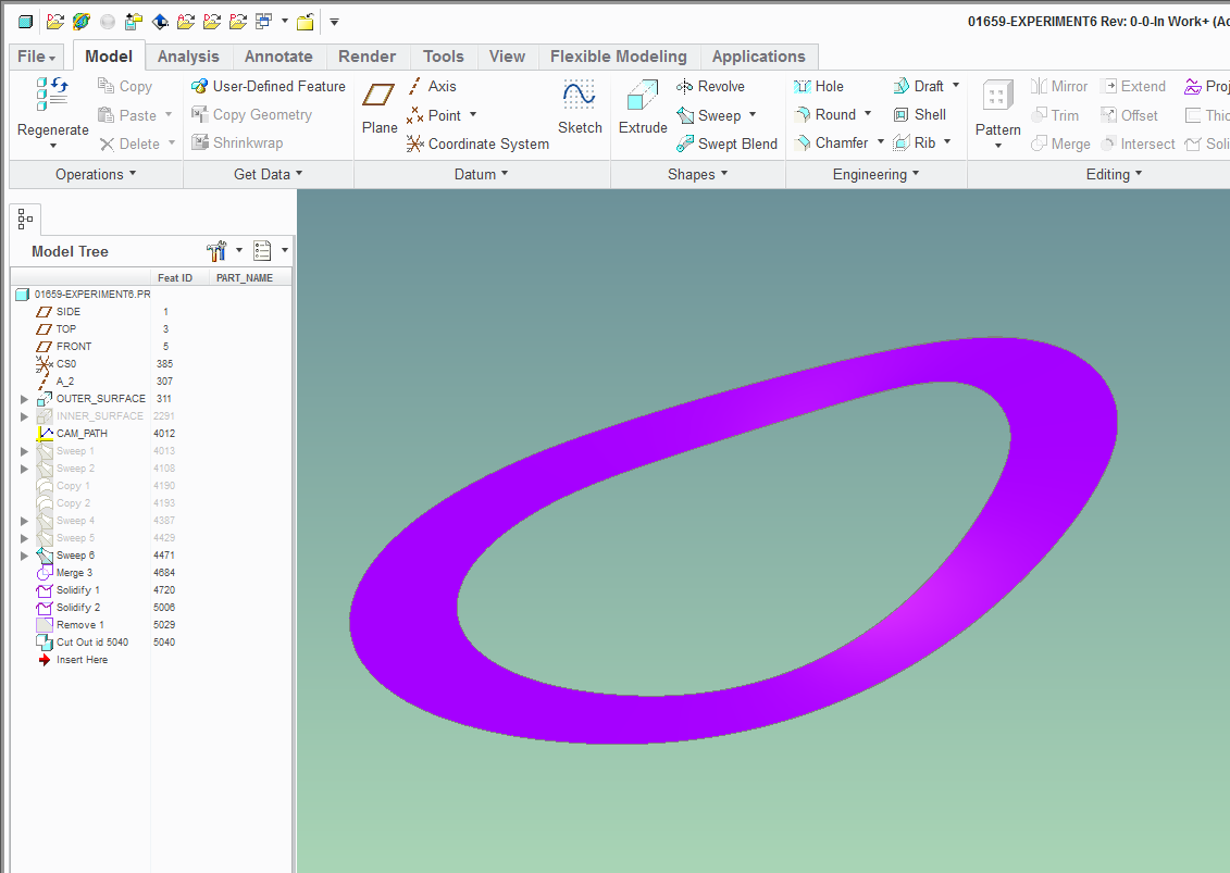
Hello everyone; can someone please save my mind because I don't understand why the final geometries of these 2 parts are different. Attached is the assembly of experiment5.prt (gray) and 01659_experiment6.prt (purple). They have the same feature tree, because the latter is a copy of the former.
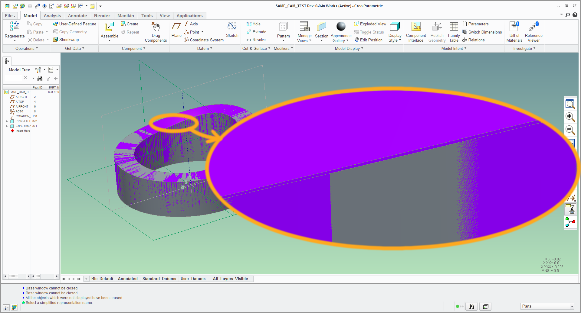
FYI, I edited the definition of some sweeps in the copy as I was trying to learn the modeling technique. I don't think I made any changes, but clearly something is different.
I'm using Creo 2.0 M160.
This thread is inactive and closed by the PTC Community Management Team. If you would like to provide a reply and re-open this thread, please notify the moderator and reference the thread. You may also use "Start a topic" button to ask a new question. Please be sure to include what version of the PTC product you are using so another community member knowledgeable about your version may be able to assist.
Solved! Go to Solution.
Labels:
- Labels:
-
Assembly Design
1 ACCEPTED SOLUTION
Accepted Solutions
Jul 29, 2015
01:06 AM
- Mark as New
- Bookmark
- Subscribe
- Mute
- Subscribe to RSS Feed
- Permalink
- Notify Moderator
11 REPLIES 11
Jul 28, 2015
12:35 PM
- Mark as New
- Bookmark
- Subscribe
- Mute
- Subscribe to RSS Feed
- Permalink
- Notify Moderator
Jul 28, 2015
12:35 PM
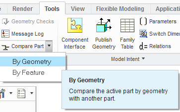
I haven't opened your files, but have you done a compare part by geometry to verify that they are actually different and its not just a graphics issue?
Jul 28, 2015
12:49 PM
- Mark as New
- Bookmark
- Subscribe
- Mute
- Subscribe to RSS Feed
- Permalink
- Notify Moderator
Jul 28, 2015
12:49 PM
for the graphic side, you may also try changing your shade quality from default 3 to 10
file > options > model display > set shade quality to: <10>
Jul 28, 2015
01:06 PM
- Mark as New
- Bookmark
- Subscribe
- Mute
- Subscribe to RSS Feed
- Permalink
- Notify Moderator
Jul 28, 2015
01:06 PM
Also, compare by feature will tell you if you accidentally made changes when querying the model.
Jul 28, 2015
01:18 PM
- Mark as New
- Bookmark
- Subscribe
- Mute
- Subscribe to RSS Feed
- Permalink
- Notify Moderator
Jul 28, 2015
01:18 PM
What started me on this silly quest is when I was reviewing playbacks of the mechanism analysis and saw interference between the copied cam and the follower and there was no such interference between the original cam and the follower.
But thanks for the tip about the comparison tool; Geometrical comparison shows a difference:
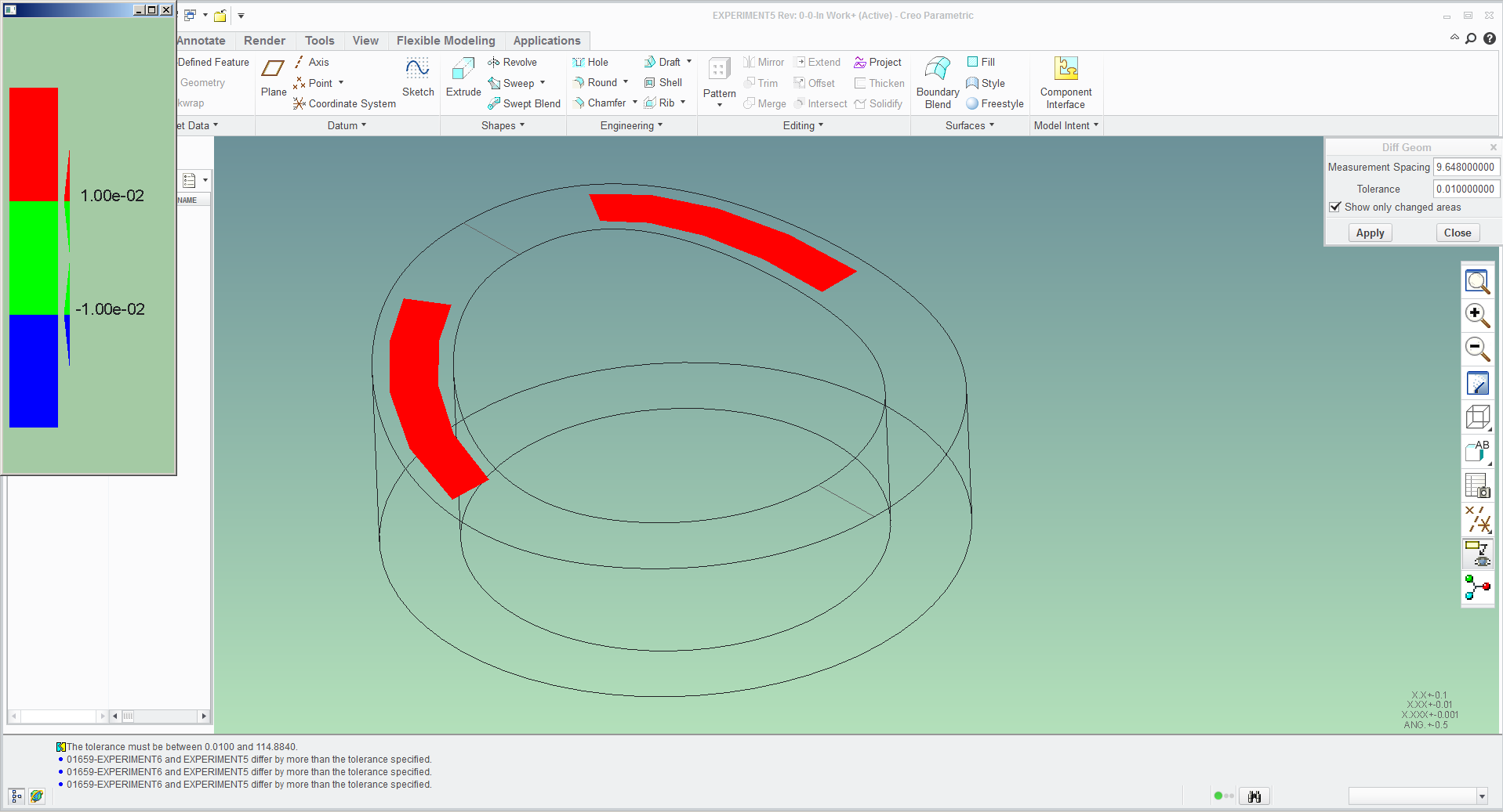
I did do another check, which is cutting out one part out of the other:
So I don't think that it's a graphics artifact - the copy is somehow "larger" than the original. I've been visually checking the geometries (by highlighting features) and it seems that up to the "Sweep 6" feature, surfaces and curves they are identical in both.
But when I examine "Sweep 6" definition, I can't spot where there is a difference. I need another set of eyes...
Jul 28, 2015
01:37 PM
- Mark as New
- Bookmark
- Subscribe
- Mute
- Subscribe to RSS Feed
- Permalink
- Notify Moderator
Jul 28, 2015
01:37 PM
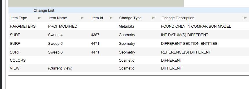
Compare by feature shows that sweep 4 and sweep 6 are different:
Jul 28, 2015
03:16 PM
- Mark as New
- Bookmark
- Subscribe
- Mute
- Subscribe to RSS Feed
- Permalink
- Notify Moderator
Jul 28, 2015
03:16 PM
Yeah, I did this as well. At least this comparison tool is a useful tidbit I got to know from this fiasco.
Problem is, the tool tells me there is a difference, but I don't see it. In both parts, the Sweep 4 feature has the same definition, the same references, the same information on the "info" page, so what the heck? what is actually different? I don't know what INT DATUM is...
this is very frustrating. What the heck, I'll send it to PTC and see what they say about it.
Jul 28, 2015
03:48 PM
- Mark as New
- Bookmark
- Subscribe
- Mute
- Subscribe to RSS Feed
- Permalink
- Notify Moderator
Jul 28, 2015
03:48 PM
I would assume that means "internal datum". Perhaps a datum on the fly? I didn't dig into the parts, I jsut ran the anaylsis.
Good luck, let us know what PTC says.
Jul 28, 2015
06:05 PM
- Mark as New
- Bookmark
- Subscribe
- Mute
- Subscribe to RSS Feed
- Permalink
- Notify Moderator
Jul 28, 2015
06:05 PM
the models have been forwarded to the PTC development team. the PTC support guy didn't seem to be optimistic about them actually finding what specific procedure produced this change in geometry.
Hopefully, they'll look at it as a bug to be fixed - that is, admit that the geometry of both models should be the same and work on a resolution.
This whole cam-building synthesis experience has really been an eye-opener that has raised serious doubts about the creo modeling engine. I've generated similar, but not quite the same cam geometries using various combinations of sweep techniques (I was expecting the results to be the same).
The model I pulled from this forum (551-016_BARREL_CAM_V5_TM), adapted to the actual timing profile and size of my cam seemed to produce the best results. Funny thing is that I cannot reproduce its geometry if I try to make a replica from scratch using the same features and techniques.
And if I save-as a working copy of it, it's worrisome to see that I can break it by essentially "looking" at it...
Jul 29, 2015
06:18 AM
- Mark as New
- Bookmark
- Subscribe
- Mute
- Subscribe to RSS Feed
- Permalink
- Notify Moderator
Jul 29, 2015
06:18 AM
Did you check the accuracies?
You mentioned that you pulled the file from this forum then copied it in your environment.
Maybe you transferred / pushed your template onto the copied model.
Just a thought.
Jul 29, 2015
01:06 AM
- Mark as New
- Bookmark
- Subscribe
- Mute
- Subscribe to RSS Feed
- Permalink
- Notify Moderator
Jul 29, 2015
01:06 AM
Jul 29, 2015
08:57 AM
- Mark as New
- Bookmark
- Subscribe
- Mute
- Subscribe to RSS Feed
- Permalink
- Notify Moderator
Jul 29, 2015
08:57 AM
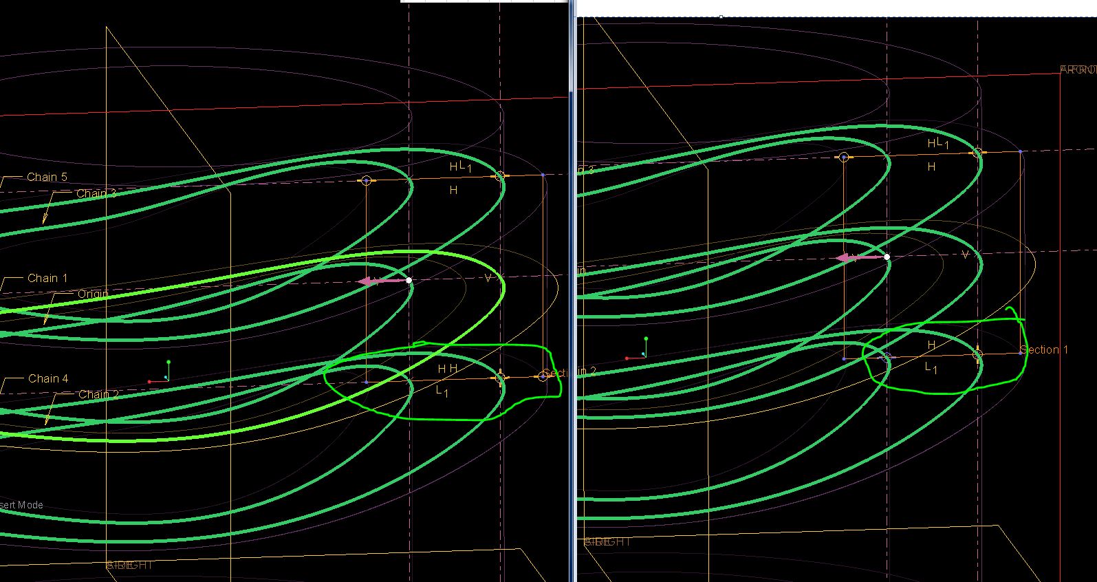
Brilliant! Thanks Matt! It seems so obvious when you highlight it like this 
I see that I did mess up the sweep cross-section. In the copy, the coincident constraint on the inner trajectory, whereas in the original, it is on the outer trajectory.
I suppose I still don't understand why that makes the difference for I thought these trajectory points are "horizontal" anyway...
Thank you everyone for your help.
