
Turn on suggestions
Auto-suggest helps you quickly narrow down your search results by suggesting possible matches as you type.
Showing results for
Turn on suggestions
Auto-suggest helps you quickly narrow down your search results by suggesting possible matches as you type.
Showing results for
Community Tip - Want the oppurtunity to discuss enhancements to PTC products? Join a working group! X
- Community
- Creo+ and Creo Parametric
- 3D Part & Assembly Design
- Re: Issues with Using Creo Simulate Fasteners with...
Options
- Subscribe to RSS Feed
- Mark Topic as New
- Mark Topic as Read
- Float this Topic for Current User
- Bookmark
- Subscribe
- Mute
- Printer Friendly Page
Issues with Using Creo Simulate Fasteners with Through and Blind Holes?
Jul 08, 2016
07:55 AM
- Mark as New
- Bookmark
- Subscribe
- Mute
- Subscribe to RSS Feed
- Permalink
- Notify Moderator
Jul 08, 2016
07:55 AM
Issues with Using Creo Simulate Fasteners with Through and Blind Holes?
HI,
Has anyone found a way to get Creo Simulate fasteners to work with Through and Blind Holes that have Draft applied to them or do we need to request an enhancement?
Appreciate any tips you have with dealing with this issue. I'm currently forced to either work around this problem by using solid models of the fasteners with preload or beam elements.
Thanks for any insight you can give me on this,
Don Anderson
This thread is inactive and closed by the PTC Community Management Team. If you would like to provide a reply and re-open this thread, please notify the moderator and reference the thread. You may also use "Start a topic" button to ask a new question. Please be sure to include what version of the PTC product you are using so another community member knowledgeable about your version may be able to assist.
Solved! Go to Solution.
Labels:
- Labels:
-
Product Insight
1 ACCEPTED SOLUTION
Accepted Solutions
Jul 08, 2016
11:00 AM
- Mark as New
- Bookmark
- Subscribe
- Mute
- Subscribe to RSS Feed
- Permalink
- Notify Moderator
Jul 08, 2016
11:00 AM
Don,
Holes have to be cylindrical or Simulate doesn't like it. One has to remove the draft.
It could pick the smallest diameter as it currently does. We always manually change the fastener diameter after anyway. Simple fasteners' separation spring stiffness calculation would be slightly different as the frustum cone would have an inner conical hole rather than cylindrical one. If contact is used then the structural stiffness is not estimated.
Not sure what you are doing with surface regions and possibly got the wrong end of the stick here - To stop the screw in the blind hole short of part 3 - put a small, structurally insignificant step to a smaller diameter near the bottom where your screw stops and choose this as your end reference.
Is the ground spring anti-rotation?
6 REPLIES 6
Jul 08, 2016
08:57 AM
- Mark as New
- Bookmark
- Subscribe
- Mute
- Subscribe to RSS Feed
- Permalink
- Notify Moderator
Jul 08, 2016
08:57 AM
Hi Steven,
Sorry, I should have posted a image of the issue.
I have also tried using surface regions to stop the fastener short of hitting part 3. Would like to use a plain Creo Fastener.
The fasteners related to the holes in part 1 which have draft are not being evaluated during the simulation run.
Thanks for looking at this,
Don

Jul 08, 2016
11:00 AM
- Mark as New
- Bookmark
- Subscribe
- Mute
- Subscribe to RSS Feed
- Permalink
- Notify Moderator
Jul 08, 2016
11:00 AM
Don,
Holes have to be cylindrical or Simulate doesn't like it. One has to remove the draft.
It could pick the smallest diameter as it currently does. We always manually change the fastener diameter after anyway. Simple fasteners' separation spring stiffness calculation would be slightly different as the frustum cone would have an inner conical hole rather than cylindrical one. If contact is used then the structural stiffness is not estimated.
Not sure what you are doing with surface regions and possibly got the wrong end of the stick here - To stop the screw in the blind hole short of part 3 - put a small, structurally insignificant step to a smaller diameter near the bottom where your screw stops and choose this as your end reference.
Is the ground spring anti-rotation?
Jul 08, 2016
11:59 AM
- Mark as New
- Bookmark
- Subscribe
- Mute
- Subscribe to RSS Feed
- Permalink
- Notify Moderator
Jul 08, 2016
11:59 AM
Hi Charles,
Thanks for confirming that Simulate fastener features do not work with drafted holes. That was kind of what I had determined with the testing I have done so far.
Yes, the ground springs are for anti-rotation of the parts that have contacts fully defined.
When I was trying the simulation with just simple Creo Simulate Fastener feature I had no contact regions defined between the parts. I let the Simulate fastener feature control the separation of the parts.
Unfortunately I'm not able to simplify the model for the testing I'm going now do to the current structure geometry.
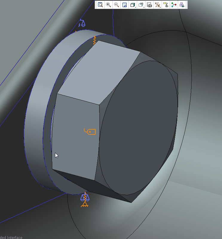
The second image above shows what I'm currently using for my joint setup where I have fully modeled the joint with solids and have fully added contacts, preload, etc.
I was hoping to start out with simple Simulate fasteners to shake out the model setup before adding all of the additional solid models and contacts.
Thanks
Don Anderosn
Jul 08, 2016
01:13 PM
- Mark as New
- Bookmark
- Subscribe
- Mute
- Subscribe to RSS Feed
- Permalink
- Notify Moderator
Jul 08, 2016
01:13 PM
Don,
Minor point re ground spring ,,, it may be better to link adjacent parts with point to point springs back to a constrained part rather than parts to ground. 2 reasons
- I know the ground spring is 'lightweight' but rigid body motions are greater then relative movement of parts. Large relative movements of contacting surfaces make a slower contact solution
- Another external load is being introduced that does not exist
Jul 08, 2016
01:46 PM
- Mark as New
- Bookmark
- Subscribe
- Mute
- Subscribe to RSS Feed
- Permalink
- Notify Moderator
Jul 08, 2016
01:46 PM
Hi Charles,
Good points on the ground springs. Thank you very much for the insight!
Don
Jul 08, 2016
11:05 AM
- Mark as New
- Bookmark
- Subscribe
- Mute
- Subscribe to RSS Feed
- Permalink
- Notify Moderator
Jul 08, 2016
11:05 AM
forgot the picture ... small step

