
Turn on suggestions
Auto-suggest helps you quickly narrow down your search results by suggesting possible matches as you type.
Showing results for
Turn on suggestions
Auto-suggest helps you quickly narrow down your search results by suggesting possible matches as you type.
Showing results for
Community Tip - Did you get an answer that solved your problem? Please mark it as an Accepted Solution so others with the same problem can find the answer easily. X
- Community
- Creo+ and Creo Parametric
- 3D Part & Assembly Design
- Re: Simulate Idea
Options
- Subscribe to RSS Feed
- Mark Topic as New
- Mark Topic as Read
- Float this Topic for Current User
- Bookmark
- Subscribe
- Mute
- Printer Friendly Page
Simulate Idea
Mar 10, 2016
05:05 PM
- Mark as New
- Bookmark
- Subscribe
- Mute
- Subscribe to RSS Feed
- Permalink
- Notify Moderator
Mar 10, 2016
05:05 PM
Simulate Idea
Hello,
Simulate lets you perform analysis using symmetries (either cyclic or mirror). The problem is that in order to use symmetries, you have to create the part or assembly using Creo.
It should be cool if simulate allows you to cut or remove material from a non-creo model. In that way, you can simulate a turbine modeled in Catia or Solidworks using symmetries, avoiding that your computer fries with each blade.
That's all.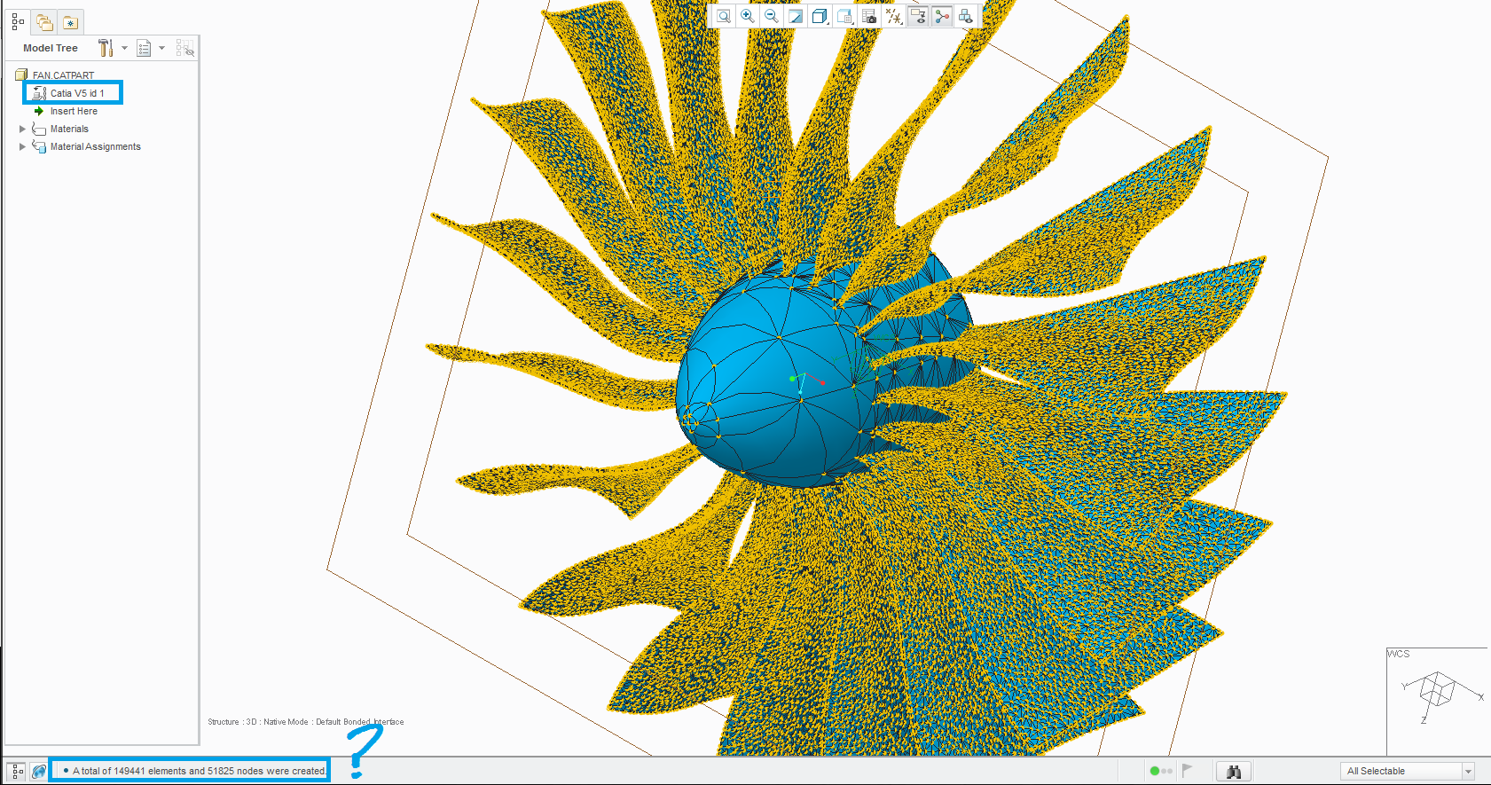
This thread is inactive and closed by the PTC Community Management Team. If you would like to provide a reply and re-open this thread, please notify the moderator and reference the thread. You may also use "Start a topic" button to ask a new question. Please be sure to include what version of the PTC product you are using so another community member knowledgeable about your version may be able to assist.
Labels:
- Labels:
-
Assembly Design
12 REPLIES 12
Mar 11, 2016
04:24 AM
- Mark as New
- Bookmark
- Subscribe
- Mute
- Subscribe to RSS Feed
- Permalink
- Notify Moderator
Mar 11, 2016
04:24 AM
You can easily cut a model created in non-Creo CAD system, this works fine. If it's a surface model (i.e. iges), you might need to patch up your surface so that it becomes "water-tight", then solidify it. With STEP, if exported as a solid, you can add/remove geometry, add rounds/holes etc. as usual. With the "feature recognition tool" you can "parameterize" rounds, chamfers, holes etc. so that you get features in the model tree, with parametric control.... I don't have experience from other tools, but in my view Creo is a great tool for manipulating imported geometry. Provided you have a Creo Parametric license of course... Otherwise you can just ask the creator/owner of the orignial CAD-file to cut it for you.
Mar 11, 2016
07:09 AM
- Mark as New
- Bookmark
- Subscribe
- Mute
- Subscribe to RSS Feed
- Permalink
- Notify Moderator
Mar 11, 2016
07:09 AM
Now I realize that I can (as an assembly part).
Can you explain me how this work: "With the "feature recognition tool" you can "parameterize" rounds, chamfers, holes etc."
Thank you.
Mar 11, 2016
07:29 AM
- Mark as New
- Bookmark
- Subscribe
- Mute
- Subscribe to RSS Feed
- Permalink
- Notify Moderator
Mar 11, 2016
07:29 AM
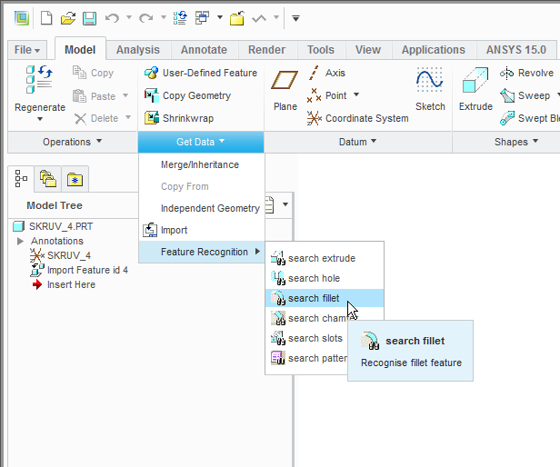
The feature recognition tool is under the "Get data"-menu, see picture below. For example, if you want to turn a fillet into a regular round-feature that you want to modify or delete, click "Search fillet", click on the fillet, and then "OK". Your model will appear identical, but in the model tree, you will see two new features. First a "remove"-feature that removes the fillet. Then you will see a new "round" that reproduces the previous fillet with a new parametric "Creo-round".
I mostly use it to delete fillets,chamfers etc. from an imported model. In such cases I first use the "feature recognition tool" and then I simply delete the round/chamfer etc. and keep only the "remove"-feature.
I hope it helps...
B.R. Mats L
Mar 11, 2016
07:57 AM
- Mark as New
- Bookmark
- Subscribe
- Mute
- Subscribe to RSS Feed
- Permalink
- Notify Moderator
Mar 11, 2016
07:57 AM
Excellent information.
Thank you!
Mar 11, 2016
08:36 AM
- Mark as New
- Bookmark
- Subscribe
- Mute
- Subscribe to RSS Feed
- Permalink
- Notify Moderator
Mar 11, 2016
08:36 AM
I don't think this Feature Recognition is part of standard Creo/Parametric.
In any case, I do not have it in my Creo2 here at work, which has the following options:
| 347 | Freestyle_Design_Extension | ModelCHECK | |
| 4DNavigator | HARNESS-MFG | NOTEBOOK | |
| AE | INTERFACE | Options_Modeler_Basic | |
| ASSEMBLY | INTF-CADDS5 | PHOTORENDER | |
| Behavioral_Modeler | INTF-CADDS5 | PIPING | |
| CABLING | INTF_for_STEP | PLOT | |
| CDT | Import_Data_Doctor | PROCESS_ASM | |
| COMPOSITE | Interactive_Surface_Design | REPORT | |
| Collaboration | Intralink_8_0 | SCAN_TOOLS | |
| DATA_for_PDGS | LEGACY | SHEETMTL-DES | |
| DETAIL | LIBRARYACCESS | SURFACE | |
| Design_Animation | Layout_3D_Integration | Truly_Heterogenous_Assembly | |
| ECAD | Manikin | WELDING | |
| FEATURE | Mechanism_Design | Web.Link | |
| Flexible_Modeling | Mechanism_Dynamics | Web.Publish |
Mar 14, 2016
11:03 AM
- Mark as New
- Bookmark
- Subscribe
- Mute
- Subscribe to RSS Feed
- Permalink
- Notify Moderator
Mar 14, 2016
11:03 AM
As I understand it, FRT does not require any additional license, bút you need to set a config option,
From PTC support:
| Resolution | For Creo Parametric 1.0, 2.0 and 3.0
|
|---|
https://support.ptc.com/appserver/cs/view/solution.jsp?n=CS28594
Mar 14, 2016
11:07 AM
- Mark as New
- Bookmark
- Subscribe
- Mute
- Subscribe to RSS Feed
- Permalink
- Notify Moderator
Mar 14, 2016
11:07 AM
Ooh - does this mean it's available in Creo 2? I'd been under the impression it was a Creo 3 enhancement.
Mar 14, 2016
11:15 AM
- Mark as New
- Bookmark
- Subscribe
- Mute
- Subscribe to RSS Feed
- Permalink
- Notify Moderator
Mar 14, 2016
11:15 AM
Yes it is, just tried it. Thanks for explaining Mads 
It even works okay, though it seems to have some quirks. Selecting a hole surface did not work, selecting an edge worked okay. (On a simple hole with straight surfaces on both ends, in what is a small but quite complex STEP file of a machined casted part).
Mar 14, 2016
11:16 AM
- Mark as New
- Bookmark
- Subscribe
- Mute
- Subscribe to RSS Feed
- Permalink
- Notify Moderator
Mar 14, 2016
11:16 AM
Yes, it's in Creo 2. I use it all the time when I deal with imported geometry. Even if it is native Creo geometry, it is sometimes convenient to export a step-file that I then re-import to work on that instead of the original Creo file. When I prepare a CAD-model for analysis, it is sometimes a lot of work to change something if the model tree lights up like a christmas tree when you try to change something. With a step export-import, you eliminate all dependencies.
Mar 23, 2016
08:44 AM
- Mark as New
- Bookmark
- Subscribe
- Mute
- Subscribe to RSS Feed
- Permalink
- Notify Moderator
Mar 23, 2016
08:44 AM
No, in this case I would typically suppress rounds/holes etc. in the original Creo file. Good modeling practice means keeping rounds chamfers etc late in the model tree, if this is applied then it is usually easy to get rid of such features. If you have a lot of references that would be affected by suppressing for example a hole, then I might use the export-import technique, and remove the hole in the imported "dead" geometry.
Mar 23, 2016
10:29 AM
- Mark as New
- Bookmark
- Subscribe
- Mute
- Subscribe to RSS Feed
- Permalink
- Notify Moderator
Mar 23, 2016
10:29 AM
You work for the only company that I know of which has a Reverse Engineering Department 
Mar 24, 2016
02:22 PM
- Mark as New
- Bookmark
- Subscribe
- Mute
- Subscribe to RSS Feed
- Permalink
- Notify Moderator
Mar 24, 2016
02:22 PM
Yes! Uniform thickness and I shell them, this was only an exaggerate mesh about the problem of removing material. I am still unable to use the FRT, it just doesn't appear. Can you upload the model of your picture?
