
Turn on suggestions
Auto-suggest helps you quickly narrow down your search results by suggesting possible matches as you type.
Showing results for
Turn on suggestions
Auto-suggest helps you quickly narrow down your search results by suggesting possible matches as you type.
Showing results for
Community Tip - Stay updated on what is happening on the PTC Community by subscribing to PTC Community Announcements. X
- Community
- Creo+ and Creo Parametric
- 3D Part & Assembly Design
- Skeleton Theory
Options
- Subscribe to RSS Feed
- Mark Topic as New
- Mark Topic as Read
- Float this Topic for Current User
- Bookmark
- Subscribe
- Mute
- Printer Friendly Page
Skeleton Theory
May 20, 2016
10:33 AM
- Mark as New
- Bookmark
- Subscribe
- Mute
- Subscribe to RSS Feed
- Permalink
- Notify Moderator
May 20, 2016
10:33 AM
Skeleton Theory
Long time UG/NX user and have been on Creo 2.0 for about 6 months. Long story, but I have several parts in a -1 assembly "floating in space". In order to avoid external references to the next higher assembly, I created a skeleton part in my -1 assy. If I understand the skeleton theory, one way is to import quilt surfaces from the next higher assy and I can use them in my skeleton to position my parts to. I think you can also use csys (coordinate systems). Since my parts are already in the right postion, what I tried doing is creating csys in my skeleton using my part in my assembly. I have a green model status, but if I run ModelCheck, it tells me I have a circular reference. Is a circular reference ok in the context of a skeleton or is there a better way to create a csys in my skeleton from the current positions of my models? Thanks
This thread is inactive and closed by the PTC Community Management Team. If you would like to provide a reply and re-open this thread, please notify the moderator and reference the thread. You may also use "Start a topic" button to ask a new question. Please be sure to include what version of the PTC product you are using so another community member knowledgeable about your version may be able to assist.
Solved! Go to Solution.
Labels:
- Labels:
-
Assembly Design
1 ACCEPTED SOLUTION
Accepted Solutions
May 24, 2016
02:25 PM
- Mark as New
- Bookmark
- Subscribe
- Mute
- Subscribe to RSS Feed
- Permalink
- Notify Moderator
May 24, 2016
02:25 PM
Skeletons are very useful / powerful design tool... That being said you need to know how to use them in ProE / CREO
the Skeleton ideally is the 1st thing you create at the beginning of the project, laying out where major components / sub assemblies etc... are.
Then in the skeleton you create separate publish geometry features "named logically" for each or the major component / sub assemblies to be passed DOWN to the components / sub assemblies buy using copy geometry.... and selecting the appropriate publish geometry feature "named logically" from the skeleton.
In this way one of the 1st things in your model tree of your components / sub assemblies is going to be the copied geometry from the Skeleton... as the design begins to take shape and changes need to be done... the changes can be done in the skeleton model and these changes propagate to all the models where the publish / copy geometry features have been used...
It's is called top down design...
I recommend starting with a simple example project and then as you gain understanding of how it all works you can apply it to larger more complex projects.
look for examples on the web.
Dave
18 REPLIES 18
May 20, 2016
08:04 PM
- Mark as New
- Bookmark
- Subscribe
- Mute
- Subscribe to RSS Feed
- Permalink
- Notify Moderator
May 20, 2016
08:04 PM
Mark,
First, circular references are never a good thing and you must work to get rid of them. Most likely you have tagged a part reference within an assembly. They are easy to find with Reference Viewer. With that said, what I am about to tell you is from an Old School Creo Cad Monkey. You will find two school's of thought when it comes to Skeleton models. One school is, "he-LL no" and the other school is "he-LL yeah". each have their advantages and disadvantages. The first disclaimer is you never have to use a skeleton if you don't need/want to. Many "he-LL yeah" advocates will tell you it is the only way to model where as the "he-LL no" advocates will tell you it's more trouble than it's worth. I tend to fall into the "he-LL no" camp. I use a Top Down without adding the extra Skeleton in the mix. You should look into Publish Geometry and drive that to lower models from an upper level model, whether it be from a skeleton or a simple "basis" model.
P.S. Being an NX user you will need to change your mindset away from "coordinate system" driven modeling to World Coordinate System modeling. You can certainly model like NX but it's not the optimum methodology in Creo. Datum on the Fly is your friend.
Cheers...
May 20, 2016
08:09 PM
- Mark as New
- Bookmark
- Subscribe
- Mute
- Subscribe to RSS Feed
- Permalink
- Notify Moderator
May 20, 2016
08:09 PM
That's exactly how to create a circular reference - which is not a desirable result. How does Creo know where to put the parts? At the CSYSs. How does Creo know where the CSYSs go? Aligned to the parts. It's a basic chicken-egg problem.
Often skeleton parts are used to specifically carry references to the top-most assembly, as a way to pre-define geometry for use in lower parts. It is important that the skeleton not be based on any of those parts.
I guess you could save an IGES or STEP file and include the coordinate systems and then re-import it into the skeleton, then delete the items that you don't want and keep the CSYSs.
I think there is a way to capture the transform between coordinate systems and use that to create independent CSYSs to drive the ones currently driven by references to the parts.
May 24, 2016
10:38 AM
- Mark as New
- Bookmark
- Subscribe
- Mute
- Subscribe to RSS Feed
- Permalink
- Notify Moderator
May 24, 2016
10:38 AM
The Skeleton shouldn't be referenced to anything. It is the back bone to the top level. The easiest thing for you to do at this point is recreate the skeleton using the information you already have for placement.
Alright, say you have a components location and need to add it to the skeleton.
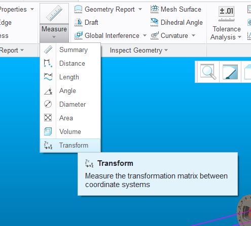
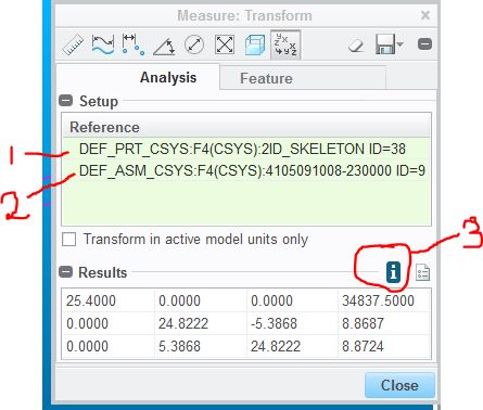
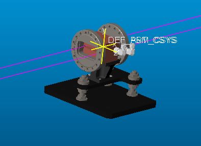
Measure the distance from the default csys from the skel to the component and save this info.
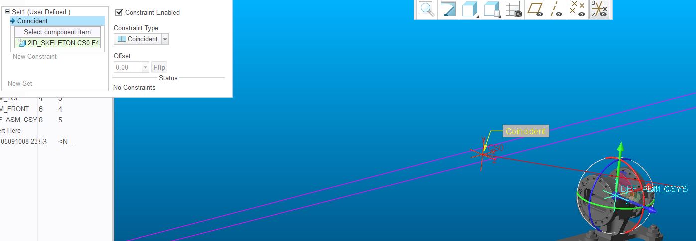
Then open the skeleton and create a csys. Select the same default as you did in the assembly.
Now change the type to "From File".
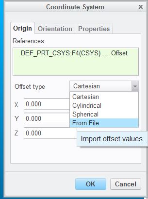
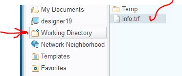
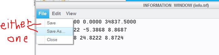
This file will be located in you working directory. Then complete this action.
Now you can go back into the assembly and redefine the placement of the component to use the newly created csys.
As many said above, there are pro's & con's about everything.
Also a million ways to do the same thing, so this is just one way.
Hope this helps.
May 24, 2016
01:46 PM
- Mark as New
- Bookmark
- Subscribe
- Mute
- Subscribe to RSS Feed
- Permalink
- Notify Moderator
May 24, 2016
01:46 PM
 John, then what's the point of the Skeleton? If you are only using it as a "backdrop" with nothing being driven by it then you are missing its function.
May 24, 2016
02:14 PM
- Mark as New
- Bookmark
- Subscribe
- Mute
- Subscribe to RSS Feed
- Permalink
- Notify Moderator
May 24, 2016
02:14 PM
I agree that would be dumb.
Once you create the new csys in the skel and redefine the location based off of the skel, then those components locations are now driven by the skeleton.
This is basically in this kind of situation, since prior information has already been defined and you're trying to readjust the control to the top.
May 24, 2016
01:23 PM
- Mark as New
- Bookmark
- Subscribe
- Mute
- Subscribe to RSS Feed
- Permalink
- Notify Moderator
May 24, 2016
01:23 PM
The reason that Creo creates a circular ref here is, if I understand properly, that it must regenerate everything from the top of the tree down.
So, first up is your skeleton. In order to regen it, it has to know where the parts are to locate the CS that you created. But it can't position the parts until it's finished regenerating the skeleton. Even if the parts aren't tied back to the skeleton, that's still a circular reference simply because of the regen order.
BTW - I'm definitely in the Heck-Yeah camp on skeletons. Very powerful tool for managing your design intent from the top on down. I rarely do anything without a skeleton and on large assys I might have 300+ features in my main skeleton plus several sub assy skeletons with a couple hundred features each as well. It's one of the techniques that allow us to dramatically shorten development time. Like a full production release of a k-cup brewer for one client from clean sheet to full tooling release in 13 weeks. We couldn't do it without extensive use of skeletons.
One of the key rules for using a skeleton is never pass geometry up the tree (or "sideways"), always pass it down. From skeleton to part or from upper level skeleton to lower level skeleton.
May 24, 2016
02:46 PM
- Mark as New
- Bookmark
- Subscribe
- Mute
- Subscribe to RSS Feed
- Permalink
- Notify Moderator
May 24, 2016
02:46 PM
Doug, you know I am your ally, right! So no flame intended. I like the Skel theory in general. But I will say it can get hairy managing the fallout when things change drastically/frequently with regard to the individual "stuff" that is within the Pub's (surfaces, quilts, points, curves, axes, etc...). When that stuff is deleted up top...it can be a pain to put all the toys back into the toy box. I find it a judgment call whether or not to use a Skel. I have done plenty with and without the extra up top.
If I were on the Witness Stand, I would vote 51% yea/49% nay.

May 24, 2016
03:11 PM
- Mark as New
- Bookmark
- Subscribe
- Mute
- Subscribe to RSS Feed
- Permalink
- Notify Moderator
May 24, 2016
03:11 PM
In a binary world, 51% is a yes vote, I'll take it. 
You're right, it does take consistent application and things can get harry if you arent' consistent, but the upsides are big. On that coffee maker project, in a late design review with an assy of some 4,000+ features, it was decided that the cabinet needed to either grow or shrink by 3/16". I pulled up the skeleton, made the change to a very early feature, went back to the assy and hit regen, with the client in the room watching. After regen I had a few failed areas, but nothing major and overall the database was now the new size. Without the skeleton, that change would have taken hours if not days and I couldn't have made the change in a design review.
I'm an unabashed fan of skeleton modeling.
Jun 30, 2016
10:39 AM
- Mark as New
- Bookmark
- Subscribe
- Mute
- Subscribe to RSS Feed
- Permalink
- Notify Moderator
Jun 30, 2016
10:39 AM
Doug
I use skeletons in my models and I like the fact it keeps other users working on my assemblies from moving critical dimensions/ holes etc..
One question I do have, I have seen some people use the same top level skeleton skeleton part in lower level sub-assemblies instead of publishing and copy geometry to the lower level. What disadvantages does this create? It does save a lot of work and you don't have all the copy geom in model but maybe something with regeneration...
Thanks
Jun 30, 2016
10:51 AM
- Mark as New
- Bookmark
- Subscribe
- Mute
- Subscribe to RSS Feed
- Permalink
- Notify Moderator
Jun 30, 2016
10:51 AM
Using the skeleton in the subassembly, you have ALL the info (which likely is not required).
Using copy geometry, you can be selective and "borrow" only want you need and may be easier to manage on the subassembly level.
Jun 30, 2016
12:04 PM
- Mark as New
- Bookmark
- Subscribe
- Mute
- Subscribe to RSS Feed
- Permalink
- Notify Moderator
Jun 30, 2016
12:04 PM
It seems much easier just to use the skeleton twice, It seems much easier because ALL info is there and no need to use COPY GEOM and keep changing the Publish GEOM..
I have been using the copy geom and publish method for a while but some here are just using top level skeleton in multiple places and it seems much easier. Was looking for disadvantages of doing this.
Thanks
Jun 30, 2016
11:11 AM
- Mark as New
- Bookmark
- Subscribe
- Mute
- Subscribe to RSS Feed
- Permalink
- Notify Moderator
Jun 30, 2016
11:11 AM
Having a single skeleton that you use in subassys simplifies things, but as Mark said it means that everything needs to be in that skeleton. Having sub assy skeletons also allows other users to work on those sub assy skeletons without tying up the master skeleton.
I typically do a top level skeleton and sub assy skeletons down one level. Going 3 or more levels down gets unreasonably complicated, especially if you add some top level stuff that needs to go down several levels deep:
- Add geom to top level skeleton
- Add it to pub geom in top level skeleton
- regen
- Add it to pub geom in sub assy skeleton
- regen
- Add it to publish geom in sub-sub assy skeleton
- regen
- Add it to publish geom in sub-sub-sub assy skeleton to get it to the part
- regen
- build features in part
Ugh.
Jun 30, 2016
12:05 PM
- Mark as New
- Bookmark
- Subscribe
- Mute
- Subscribe to RSS Feed
- Permalink
- Notify Moderator
Jun 30, 2016
12:05 PM
Thanks
I have been doing that also but some here are just using the top level assembly again in a lower level assemblies so allot of the copy geom goes away. For example use the same top level assy and assemble it to the chassis assembly…
May 24, 2016
02:25 PM
- Mark as New
- Bookmark
- Subscribe
- Mute
- Subscribe to RSS Feed
- Permalink
- Notify Moderator
May 24, 2016
02:25 PM
Skeletons are very useful / powerful design tool... That being said you need to know how to use them in ProE / CREO
the Skeleton ideally is the 1st thing you create at the beginning of the project, laying out where major components / sub assemblies etc... are.
Then in the skeleton you create separate publish geometry features "named logically" for each or the major component / sub assemblies to be passed DOWN to the components / sub assemblies buy using copy geometry.... and selecting the appropriate publish geometry feature "named logically" from the skeleton.
In this way one of the 1st things in your model tree of your components / sub assemblies is going to be the copied geometry from the Skeleton... as the design begins to take shape and changes need to be done... the changes can be done in the skeleton model and these changes propagate to all the models where the publish / copy geometry features have been used...
It's is called top down design...
I recommend starting with a simple example project and then as you gain understanding of how it all works you can apply it to larger more complex projects.
look for examples on the web.
Dave
May 24, 2016
03:26 PM
- Mark as New
- Bookmark
- Subscribe
- Mute
- Subscribe to RSS Feed
- Permalink
- Notify Moderator
May 24, 2016
03:26 PM
Doug, I’m impressed, sounds like you work with a team that uses parametric modeling correctly. I work in Aerospace and the upfront planning to fully utilize parametric models usually never happens. Especially when we have many NX users which all do things differently.
In my case, I copied some surface geometry from a higher assembly and converted them to independent geometry in my skeleton which now gives me reference geometry to constrain my parts to. From what I understand now, this seems to be a somewhat acceptable way of positioning the parts I have in my case and I don’t have any circular references now.
In my case, my parts are only small pieces of the puzzle of a large project, so I have to kind of work with what’s already been done. Many other skeletons have been created by others for a top down approach.
Thanks for all the replies. I learn so much more from discussions like this, than reading books on Creo or online tutorials.
May 24, 2016
04:03 PM
- Mark as New
- Bookmark
- Subscribe
- Mute
- Subscribe to RSS Feed
- Permalink
- Notify Moderator
May 24, 2016
04:03 PM
Yes, we've got a good team.
May 24, 2016
06:31 PM
- Mark as New
- Bookmark
- Subscribe
- Mute
- Subscribe to RSS Feed
- Permalink
- Notify Moderator
May 24, 2016
06:31 PM
Great description, David
Jul 01, 2016
04:48 PM
- Mark as New
- Bookmark
- Subscribe
- Mute
- Subscribe to RSS Feed
- Permalink
- Notify Moderator
Jul 01, 2016
04:48 PM
I tried to get started recently with top down design with skeletons and had to extract out of it. Publish/copy geometry did not work well because pattern referencing was lost. I did find a work around. The real show stopper was copying the assembly, particularly with a family table part that referenced the skeleton. The Save As... forced the skeleton part to be duplicated. Due to the famly table part, we ended up with this matrix of references all over the place.
I'm sure skeletons are great for a grounds-up single design, but it did not work so well for us with our various configurations and our need to leverage designs from one project to the next.
David
