
Turn on suggestions
Auto-suggest helps you quickly narrow down your search results by suggesting possible matches as you type.
Showing results for
Turn on suggestions
Auto-suggest helps you quickly narrow down your search results by suggesting possible matches as you type.
Showing results for
- Community
- Creo+ and Creo Parametric
- 3D Part & Assembly Design
- Verify the center of multiple axis in an assembly
Options
- Subscribe to RSS Feed
- Mark Topic as New
- Mark Topic as Read
- Float this Topic for Current User
- Bookmark
- Subscribe
- Mute
- Printer Friendly Page
Verify the center of multiple axis in an assembly
Aug 26, 2014
06:15 PM
- Mark as New
- Bookmark
- Subscribe
- Mute
- Subscribe to RSS Feed
- Permalink
- Notify Moderator
Aug 26, 2014
06:15 PM
Verify the center of multiple axis in an assembly
We have an assembly with multiple plates and hundreds of holes between them. Is there a simple way to verify the center of all these holes are lined up to each other, across multiple parts?
ΜΟΛΩΝ ΛΑΒΕ
This thread is inactive and closed by the PTC Community Management Team. If you would like to provide a reply and re-open this thread, please notify the moderator and reference the thread. You may also use "Start a topic" button to ask a new question. Please be sure to include what version of the PTC product you are using so another community member knowledgeable about your version may be able to assist.
Labels:
- Labels:
-
Assembly Design
2 REPLIES 2
Aug 27, 2014
08:18 AM
- Mark as New
- Bookmark
- Subscribe
- Mute
- Subscribe to RSS Feed
- Permalink
- Notify Moderator
Aug 27, 2014
08:18 AM
Damian,
Do you want numerical verification or can you live with a visual? Visual is easy, and even eaiser if the holes are on the same plane. Simply view the holes with the axes and their tags "on" and it will be very easy to see if they line up.
But, if you need numerical verification itwill be more difficult and tedious. I do not know of an "automatic" way to do this but....If the holes are in a pattern you could add points to both parts (mating surfaces)as Ref patterns and then measure distance between cooresponding points in the model tree (I.E. not selecting them in the work area). Then you can see if the net measurements are zeros. Even if the holes are not patterned you can use this method. It's just more painful to add the points.
Otherwise, maybe someone with some programming skills can suggest another method.
Aug 27, 2014
01:43 PM
- Mark as New
- Bookmark
- Subscribe
- Mute
- Subscribe to RSS Feed
- Permalink
- Notify Moderator
Aug 27, 2014
01:43 PM
This will require a little Excel manipulation, but it may work.
1. Create a Publish Geometry in each plate, selecting datums, and, using the binoculars, grab all axes. Exclude as required.
2. Create a skeleton part at the highest assembly that has all of the plates. If one exists, create a second one. (I think >= WF5)
3. Activate the skeleton and create a Copy Geom for each of the above Publish Geometry
4. Export the skeleton to an IGES file. (This may be the first time I recommended IGES since the 90's)
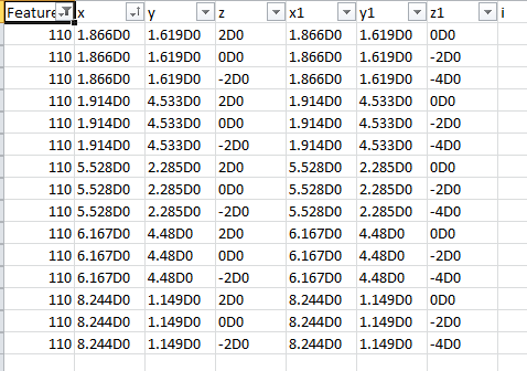
5. Open the IGES file in Excel and extract the rows pertaining to the axes. They will have a starting point and an ending point, varying in Z only.
6. Manipulate Excel to sort by X and determine some minimum offset to flag a potential issue.
Here is a look at Excel with no axis offsets. 3 parts with 5 holes each. The parts are 2 inches thick and stacked, creating the Z offset.
[cid:image002.png@01CFC1E3.914970C0]
J.P. Vanasse
Global IT, R&D Surgical Franchises
20511 Lake Forest Dr., Lake Forest, CA 92630, USA
T +1 949.505.7804 | F +1 949.505.6270 | M +1 714.612.3823
[cid:image001.png@01CE1FC3.11B93FC0]
1. Create a Publish Geometry in each plate, selecting datums, and, using the binoculars, grab all axes. Exclude as required.
2. Create a skeleton part at the highest assembly that has all of the plates. If one exists, create a second one. (I think >= WF5)
3. Activate the skeleton and create a Copy Geom for each of the above Publish Geometry
4. Export the skeleton to an IGES file. (This may be the first time I recommended IGES since the 90's)
5. Open the IGES file in Excel and extract the rows pertaining to the axes. They will have a starting point and an ending point, varying in Z only.
6. Manipulate Excel to sort by X and determine some minimum offset to flag a potential issue.
Here is a look at Excel with no axis offsets. 3 parts with 5 holes each. The parts are 2 inches thick and stacked, creating the Z offset.
[cid:image002.png@01CFC1E3.914970C0]
J.P. Vanasse
Global IT, R&D Surgical Franchises
20511 Lake Forest Dr., Lake Forest, CA 92630, USA
T +1 949.505.7804 | F +1 949.505.6270 | M +1 714.612.3823
[cid:image001.png@01CE1FC3.11B93FC0]
