
Turn on suggestions
Auto-suggest helps you quickly narrow down your search results by suggesting possible matches as you type.
Showing results for
Turn on suggestions
Auto-suggest helps you quickly narrow down your search results by suggesting possible matches as you type.
Showing results for
Community Tip - Want the oppurtunity to discuss enhancements to PTC products? Join a working group! X
- Community
- Creo+ and Creo Parametric
- 3D Part & Assembly Design
- WF5 and assembly cuts and bom tables
Options
- Subscribe to RSS Feed
- Mark Topic as New
- Mark Topic as Read
- Float this Topic for Current User
- Bookmark
- Subscribe
- Mute
- Printer Friendly Page
WF5 and assembly cuts and bom tables
Nov 29, 2012
12:15 PM
- Mark as New
- Bookmark
- Subscribe
- Mute
- Subscribe to RSS Feed
- Permalink
- Notify Moderator
Nov 29, 2012
12:15 PM
WF5 and assembly cuts and bom tables
I just encountered a problem where I have 2 parts in an assembly and one of them is intersected by an assembly cut. On the assembly drawing now, that part shows up as 2 separate lines on the BOM (repeat region set with no duplicates and worked fine until the assembly cut was added).
Any ideas on why it has done this? I forgot to search the knowledge base and the user group archives...I'll go do that right now.
Thanks,
This thread is inactive and closed by the PTC Community Management Team. If you would like to provide a reply and re-open this thread, please notify the moderator and reference the thread. You may also use "Start a topic" button to ask a new question. Please be sure to include what version of the PTC product you are using so another community member knowledgeable about your version may be able to assist.
Labels:
- Labels:
-
Assembly Design
19 REPLIES 19
Nov 29, 2012
03:20 PM
- Mark as New
- Bookmark
- Subscribe
- Mute
- Subscribe to RSS Feed
- Permalink
- Notify Moderator
Nov 29, 2012
03:20 PM
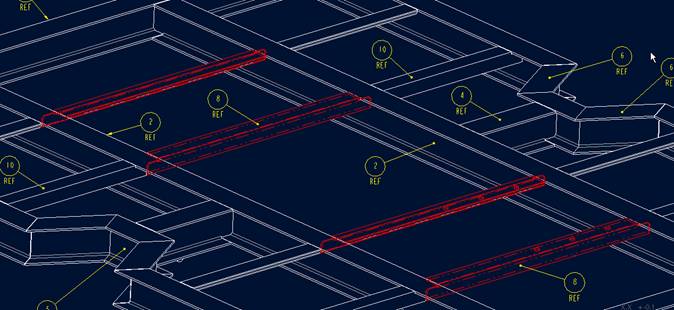
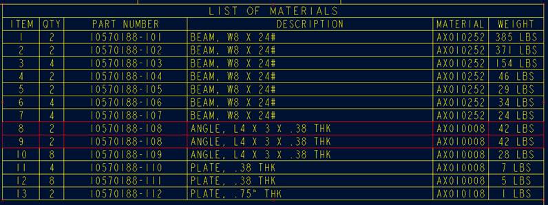
I have 4 pieces of angle iron, exactly the same but at the assy level I have to drill holes that must line up across 2 of the pieces. When I do this assembly cut, it messes up my repeat region BOM.
It's splits item 8 in two. 2 on item 8, 2 on item 9. If I delete the assembly cut, the table returns to normal.
Has anyone else seen this? I just don't remember it happening before.
[cid:image007.jpg@01CDCE34.569885F0]
[cid:image008.jpg@01CDCE34.569885F0]
[cid:image009.jpg@01CDCE34.569885F0]
It's splits item 8 in two. 2 on item 8, 2 on item 9. If I delete the assembly cut, the table returns to normal.
Has anyone else seen this? I just don't remember it happening before.
[cid:image007.jpg@01CDCE34.569885F0]
[cid:image008.jpg@01CDCE34.569885F0]
[cid:image009.jpg@01CDCE34.569885F0]
Nov 29, 2012
05:05 PM
- Mark as New
- Bookmark
- Subscribe
- Mute
- Subscribe to RSS Feed
- Permalink
- Notify Moderator
Nov 29, 2012
05:05 PM
I think you need to keep the feature from showing up at the part level.
I don't do it much, but I believe you need to set the visibility to
assembly or top level vs. part level when you create the cut feature in
assembly.
Christopher F. Gosnell
FPD Company
124 Hidden Valley Road
McMurray, PA 15317
I don't do it much, but I believe you need to set the visibility to
assembly or top level vs. part level when you create the cut feature in
assembly.
Christopher F. Gosnell
FPD Company
124 Hidden Valley Road
McMurray, PA 15317
Nov 29, 2012
05:37 PM
- Mark as New
- Bookmark
- Subscribe
- Mute
- Subscribe to RSS Feed
- Permalink
- Notify Moderator
Nov 29, 2012
05:37 PM
No, these are just ordinary assembly cuts only visible at the top level assy. The cuts don't show at the part level.
Nov 29, 2012
05:49 PM
- Mark as New
- Bookmark
- Subscribe
- Mute
- Subscribe to RSS Feed
- Permalink
- Notify Moderator
Nov 29, 2012
05:49 PM
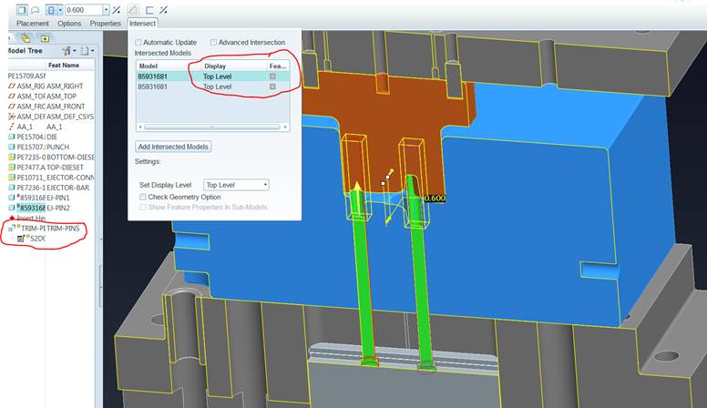
Have you made sure that the intersect option is set to manual and only the required parts are intersected?
Nov 29, 2012
06:25 PM
- Mark as New
- Bookmark
- Subscribe
- Mute
- Subscribe to RSS Feed
- Permalink
- Notify Moderator
Nov 29, 2012
06:25 PM
I've tried automatic, manual, unselecting all, selecting all the of intersected and non-intersected parts. Lots of variations. I thought maybe selecting all of the same parts for intersection even though most aren't intersected.
Maybe someone outside of my organization can try it so I will know whether it's just us or if it is a pro/e thing. I tried it on a completely separate model with a different set of parts in a completely new drawing with a newly inserted BOM table and got the same result. It's pretty simple test. Make an assembly, assemble the part in 2 different locations. Make an assy cut thru one of the 2. Make a drawing, add a repeat region BOM table and see what it does for you. I think we have ours set to either no duplicates or no duplicates/level.
Any help would be appreciated.
Steve
Nov 29, 2012
07:48 PM
- Mark as New
- Bookmark
- Subscribe
- Mute
- Subscribe to RSS Feed
- Permalink
- Notify Moderator
Nov 29, 2012
07:48 PM
Hi Steve,
It works as expected for me.... We have WF5 M060.
I tried with the second tweezer above and below the assembly level cut but
it made no difference.
Regards,
--
Mark von Huben
Principal Engineer
Cochlear Ltd
1 University Ave
Macquarie University NSW 2109
It works as expected for me.... We have WF5 M060.
I tried with the second tweezer above and below the assembly level cut but
it made no difference.
Regards,
--
Mark von Huben
Principal Engineer
Cochlear Ltd
1 University Ave
Macquarie University NSW 2109
Nov 30, 2012
04:04 AM
- Mark as New
- Bookmark
- Subscribe
- Mute
- Subscribe to RSS Feed
- Permalink
- Notify Moderator
Nov 30, 2012
04:04 AM
This issue goes back awhile ago. We are using WF3 and the problem with assembly cuts is quite the same.
Components are split in several rows in BOM, because mass properties are calculated at assembly level. Even though the parts are on the part level the same, mass gets calculated considering assembly cut and then updated in the part i.e. repeat region.
Workaround to this is to regenerate assembly to calculate correct masses for each part, then open part relation dialog box and comment the line where mass is calculated, switch to the assembly again, calculate masses and regenerate. This way assembly mass calculation does not influence the mass of each component and repeat region shows appropriate pieces of parts which are subject to assembly cut.
You only need to bear in mind, that mass calculation in the part is commented out and you need to repeat above procedure when you redefine features which affect mass of the component.
Nov 30, 2012
08:40 AM
- Mark as New
- Bookmark
- Subscribe
- Mute
- Subscribe to RSS Feed
- Permalink
- Notify Moderator
Nov 30, 2012
08:53 AM
- Mark as New
- Bookmark
- Subscribe
- Mute
- Subscribe to RSS Feed
- Permalink
- Notify Moderator
Nov 30, 2012
08:53 AM
Thank you very much. That is what the problem was. Once we took out the weight parameter from the table, the duplicate numbers went away.
I had never seen this before because this is the first place I had added a weight to the BOM table.
I had never seen this before because this is the first place I had added a weight to the BOM table.
Nov 30, 2012
10:10 AM
- Mark as New
- Bookmark
- Subscribe
- Mute
- Subscribe to RSS Feed
- Permalink
- Notify Moderator
Nov 30, 2012
10:10 AM
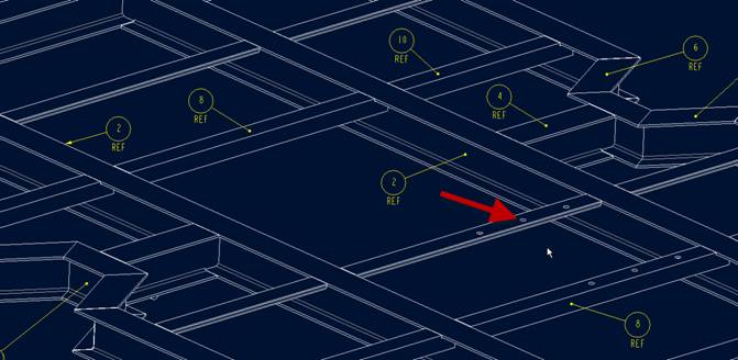
Here is an example I am working on. The image is a section view of a
forging dieset.
The green items are standard ejector pins that are cut to length at
assembly. This does not create extra items in the Assembly BOM.
BTW, I have a 'Foundation Advantage' license, and have the TDO (Tool
Design Option) available, although I don't need to have TDO active.
Good Luck
/rant
What really gets my knickers in a twist is that I can do this, but I
cannot restrict parts to avoid in-context sketcher references in
assembly without AAX.
I call BS.
/rant
Christopher F. Gosnell
FPD Company
124 Hidden Valley Road
McMurray, PA 15317
Nov 30, 2012
11:09 AM
- Mark as New
- Bookmark
- Subscribe
- Mute
- Subscribe to RSS Feed
- Permalink
- Notify Moderator
Nov 30, 2012
11:09 AM
Sorry if I misunderstood. The OP claimed that the parts had holes
drilled in assembly. I would expect you would not want these features
shown at part level.
In my case I have a standard item that I use in many assemblies, and it
needs to be trimmed to length as needed in assembly.
Now I have just read another bit of the thread that commented on the
issue of the BOM listing part mass properties possibly causing the issue
of duplicate parts shown on the BOM.
The native part level mass properties cannot be used to get a proper
assembly weight, and must be calculated at the assembly level, but I
would agree that WRT to the BOM 'weight' of the part, it seems to be
logical (to me) to show it without the assembly level holes included.
Now, the calculated weight of the assembly should include the weight
loss attributed to the assembly level cuts, and also weight increases
from things like weld beads, etc...
My BOMS don't typically show the weight of individual parts. My
assembly drawings can show the weight of the assembly to make sure the
fork truck can lift it, etc..., but I never really checked to see if by
creating assembly cuts, my weights may actually be off also.
(Wild-a** guess)
Maybe somehow the BOM functionality is 'broken' in that I can see the
system calculating a weight for a 'phantom' part on the fly that
includes the assembly cuts to come up with an accurate assembly weight.
Christopher F. Gosnell
FPD Company
124 Hidden Valley Road
McMurray, PA 15317
Nov 30, 2012
11:12 AM
- Mark as New
- Bookmark
- Subscribe
- Mute
- Subscribe to RSS Feed
- Permalink
- Notify Moderator
Nov 30, 2012
11:12 AM
Thanks Chris. I was there too. Well, I still had automatic update turned on. I had tried turning it off also. Turns out it is the weight column in the BOM that is causing the issue. Immediately upon removing the mass props from the table, all my problems were solved.
On your "cut to fit" part, have you tried flexible components?
Steve
On your "cut to fit" part, have you tried flexible components?
Steve
Nov 30, 2012
11:15 AM
- Mark as New
- Bookmark
- Subscribe
- Mute
- Subscribe to RSS Feed
- Permalink
- Notify Moderator
Nov 30, 2012
11:15 AM
I've found in the past that Pro/E will group items in a repeat region
when all the data shown in the region are the same. If your region only
contains the description parameter and two different items have the same
description they go on the same line, even if they are vastly different.
So a large weldment assy described as 'BRACKET' and a tiny piece of
angle with the same description will appear on the same line, QTY 2
(assuming you have a QTY column).
The reverse would be true, then, when two of the same part have
different mass because of an assy cut and you add the mass in the table,
Pro/E will put them on separate lines. I'd assume that as long as the
mass isn't in the table, you should be able to have the assy mass
calculated and it should work fine.
--
Nov 30, 2012
11:26 AM
- Mark as New
- Bookmark
- Subscribe
- Mute
- Subscribe to RSS Feed
- Permalink
- Notify Moderator
Nov 30, 2012
11:26 AM
I re-tested and I cut away most of one of the parts. The mass is different on items 4 and 5 in the table even though they are the same part.
It's odd and unexpected but now that I understand what is happening, I can watch out for it.
[cid:image003.png@01CDCEDC.C3778790]
It's odd and unexpected but now that I understand what is happening, I can watch out for it.
[cid:image003.png@01CDCEDC.C3778790]
Nov 30, 2012
11:50 AM
- Mark as New
- Bookmark
- Subscribe
- Mute
- Subscribe to RSS Feed
- Permalink
- Notify Moderator
Nov 30, 2012
11:50 AM
I consider that this is not a spring or some other 'flexible' component
(at least in my view). I am actually modifying the component in ways
that effects its' interchangeability.
I understand that flexible components can be very useful for cut to
length items like structural sections, etc...
I would hope that in possible future where we are using some type of
PDM/PLM and everything is unicorns and rainbows, the act of creating an
assembly cut on an item would trigger the need to understand that this
part now is not interchangeable with the 'stock' part, for MRP /
inventory purposes. (Maybe not, we don't really inventory these items
now as long as a pin 'exists' in inventory we are satisfied)
In our case, these pins are almost a 'consumable' item, but the length
must be shown as at least visually correct to avoid confusion.
Thanks for your suggestions, I will seriously consider this experiment
as time allows.
I try to keep active and help when I can, and not just 'lurk' on these
forums is because all of the 'arrows in the back' the rest of you have
taken for us with regards to flexing the muscle of this software.
Christopher F. Gosnell
FPD Company
124 Hidden Valley Road
McMurray, PA 15317
Nov 30, 2012
01:14 PM
- Mark as New
- Bookmark
- Subscribe
- Mute
- Subscribe to RSS Feed
- Permalink
- Notify Moderator
Nov 30, 2012
01:14 PM
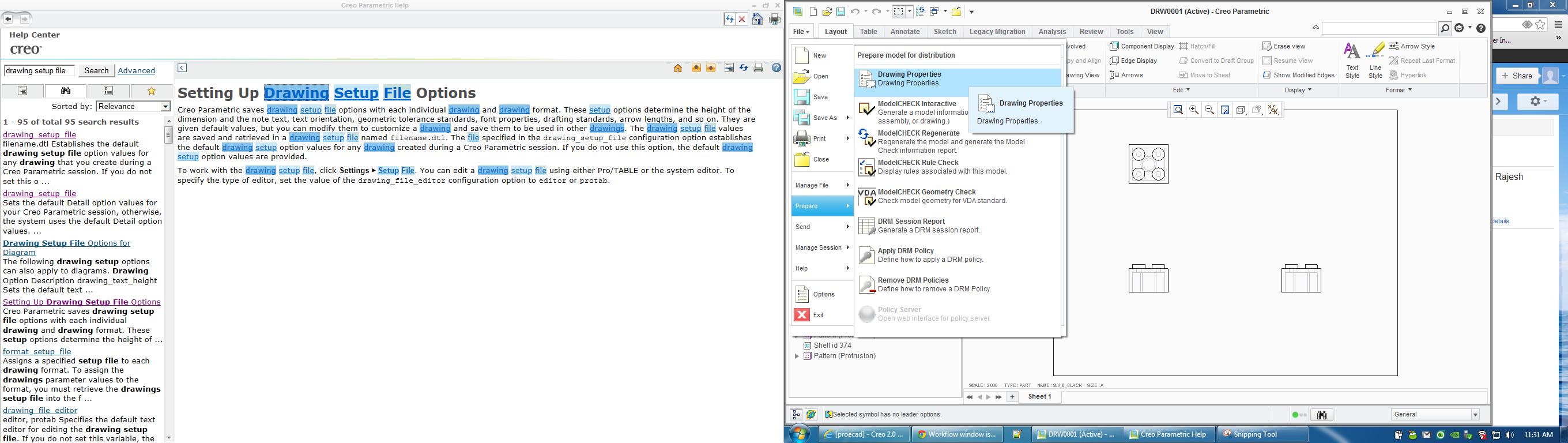
In WF3 I can right click> properties to get to drawing options. Where can I find this in Creo 2.0?
Thanks,
Patrick Fariello
CommScope
1300 E. Lookout Dr. Suite 150
Richardson, TX 75082
phone: 972-792-3303
-<blocked::<a style="COLOR:" blue;=" text-decoration:=" underline"=" target="_BLANK" href="mailto:-">">mailto:->
[cid:image002.jpg@01CDCEEB.ABE09130]
________________________________
Thanks,
Patrick Fariello
CommScope
1300 E. Lookout Dr. Suite 150
Richardson, TX 75082
phone: 972-792-3303
-<blocked::<a style="COLOR:" blue;=" text-decoration:=" underline"=" target="_BLANK" href="mailto:-">">mailto:->
[cid:image002.jpg@01CDCEEB.ABE09130]
________________________________
Nov 30, 2012
01:17 PM
- Mark as New
- Bookmark
- Subscribe
- Mute
- Subscribe to RSS Feed
- Permalink
- Notify Moderator
Nov 30, 2012
01:17 PM
The problem may be the weight column. Is that driven by the model? If so then the weight of the cut and uncut items are different.
David Haigh
David Haigh
Nov 30, 2012
01:36 PM
- Mark as New
- Bookmark
- Subscribe
- Mute
- Subscribe to RSS Feed
- Permalink
- Notify Moderator
Nov 30, 2012
01:36 PM
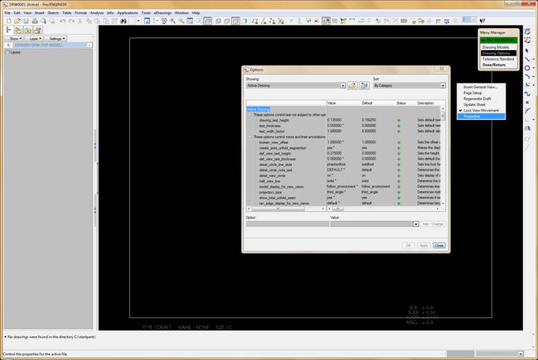
Patrick, please see attached screen shot. To access this, go to File -->
Prepare --> Drawing Properties and then select "Change" next to detail
options and this will bring up the Options window for the Drawings.
You can also add this function to the Toolbar or Quicklinks toolbar for
quicker access.
You can also use the Creo Search function to find these types of options.
Hope this helps!
Dec 03, 2012
11:02 AM
- Mark as New
- Bookmark
- Subscribe
- Mute
- Subscribe to RSS Feed
- Permalink
- Notify Moderator
Dec 03, 2012
11:02 AM
I haven't done tables in a while so I'm not sure if you can force it to handle family table instances differently, but remember that is how assembly cuts are done. The parts being cut have a hidden family table created, one with the cut and one without. The cut "instance" is then used in the assembly. It makes some sense for the assembled version to be used for mass properties in assembly since that is the condition you are asking for.
I learned about the hidden family table some years ago when I had a problem with an assembly cut, and a bug actually allowed Pro to report some useful information when it said something like "Error in family table instance #AF0". I asked our AE at the time and he confirmed that is how they are handled. It makes sense, PTC has actually come up with very little new core functionality for quite some time, they just package our already existing functionality into simple commands.
Rob Reifsnyder
Mechanical Design Engineer/ Producibility Engineer / Pro/E Librarian
[LM_Logo_Tag_RGB_NoR_r06]
