Community Tip - You can subscribe to a forum, label or individual post and receive email notifications when someone posts a new topic or reply. Learn more! X
- Community
- Creo (Previous to May 2018)
- Creo Modeling Questions
- Re: Corner blend
- Subscribe to RSS Feed
- Mark Topic as New
- Mark Topic as Read
- Float this Topic for Current User
- Bookmark
- Subscribe
- Mute
- Printer Friendly Page
Corner blend
- Mark as New
- Bookmark
- Subscribe
- Mute
- Subscribe to RSS Feed
- Permalink
- Notify Moderator
Corner blend
We are trying to model a blend on the corner of a box.
The edges of the box are square, with no blending.
Imagine taking a box and using a belt sander to only radius the corner.
How do you model this transition in Creo2?
- Mark as New
- Bookmark
- Subscribe
- Mute
- Subscribe to RSS Feed
- Permalink
- Notify Moderator
Use SolidWorks. (I'm not joking.) It's really hard to get a decent looking corner like this in Creo (with or without radii on the edges.) I've opened cases on this in the past with tech support and they couldn't figure out a good way either.
If you are willing to have some kind of radius on each edge, even a small one, you can switch the round to transition mode, pick the corner transition, and then change it to "corner sphere". Unfortunately this "dips in" in a non-realistic way (if belt sanding for example).
A different approach might be to use surface copies and vertex rounds to cut back the corners:
Unfortunately I've never been able to get a patch to work to close it back up. Probably due to the topology as mentioned here: Vertex fillet | SOLIDWORKS Forums
- Mark as New
- Bookmark
- Subscribe
- Mute
- Subscribe to RSS Feed
- Permalink
- Notify Moderator
solidworks also gives the same solution.
in creo it is a corner sphere transition.
- Mark as New
- Bookmark
- Subscribe
- Mute
- Subscribe to RSS Feed
- Permalink
- Notify Moderator
Okay, this should have been -A LOT- simpler... but it worked.
This is a sweep where the sweep wasn't the problem, it was the merge. Maybe if I started with a solid, it would have worked easier.
Regardless, a swept circle can be swept to zero diameter but an arc cannot.
Tom, I went off your lead with the surfaces.
Creo 2.0 attached
- Mark as New
- Bookmark
- Subscribe
- Mute
- Subscribe to RSS Feed
- Permalink
- Notify Moderator
Wow. That sweep is insane! I can't believe you got it to merge. I tried splitting it with the center plane and Creo wouldn't allow it. (How would you split an infinitely small point anyway?)
By the way, the difference between Creo's corner sphere and SolidWorks is that the SolidWorks one actually measures the desired radius when a section is cut through the corner. Creo isn't even close. I ran into this on a similar part. There was a specified radius for each edge and a specified radius for the corner sphere.
SolidWorks in blue, Creo in gray - same corner radius specified for both: (notice the undesirable concave shape as well)
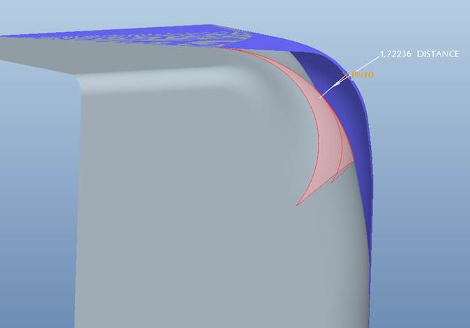
The best I could do at the time was manually build to separate variable rounds:
Next time I'm just going to send the file to you!
- Mark as New
- Bookmark
- Subscribe
- Mute
- Subscribe to RSS Feed
- Permalink
- Notify Moderator
That center "triangle" in Creo is an actual sphere, the "legs" are blended surfaces back to the cylindrical rounds along the edges. The value you give in the corner sphere is the radius of the spherical center and you can control the length of the transition area.
So Creo's transition geometry is doing what you asked it to, I haven't played with SW to see what it's doing or how it's defined.
I was able to create a 0.001" round on each leg and a 25" corner sphere transition in the center. Not exactly what the OP wants, but perhaps close enough.
- Mark as New
- Bookmark
- Subscribe
- Mute
- Subscribe to RSS Feed
- Permalink
- Notify Moderator
While not a true radius, the curvature is definitely much nicer with Antonius' method.
Antonius:
Doug:
The tips of the transition also look scary:
- Mark as New
- Bookmark
- Subscribe
- Mute
- Subscribe to RSS Feed
- Permalink
- Notify Moderator
agreed solidworks does good job in this case.
the "Fill Surface" tool in solidworks does it nicely.
- Mark as New
- Bookmark
- Subscribe
- Mute
- Subscribe to RSS Feed
- Permalink
- Notify Moderator
I can't take credit for this, I ran across the technique here years ago if I remember. The only change I made was using conics for the 2 guide curves and the section curve. I think it smooths things out even a little more (though simple arcs looked fine), plus then you can change the shape of the "radius".
- Mark as New
- Bookmark
- Subscribe
- Mute
- Subscribe to RSS Feed
- Permalink
- Notify Moderator
Frank, it really looks nice. Basically the same technique as Antonius, but without the center trajectory. The advantage of your method is that Creo will gladly split it with a plane down the middle. The full circle method didn't allow this.
I'm still amazed that Creo makes the surface with the arc length going to zero.
- Mark as New
- Bookmark
- Subscribe
- Mute
- Subscribe to RSS Feed
- Permalink
- Notify Moderator
Frank, there seems to be something unstable to this sweep. I went back to build a UDF for future use, and as soon as I change sizes either the sweep or the solidify fails. I then went back to your model and changed the cube to 2" and immediately your sweep failed as well. I tried changing accuracy but that didn't make any difference. Any ideas?
- Mark as New
- Bookmark
- Subscribe
- Mute
- Subscribe to RSS Feed
- Permalink
- Notify Moderator
I'll look at it. I played with the rho value and it worked fine....except for a value of .6, for some reason. Didn't have time to really monkey with it. Try replacing the conics with simple arcs. I changed them to conics because conics are more truly tangent, and work better for surfacing.
Yes, you can drive a surface TO zero, but not FROM zero. Also, you cannot have an arc radius go to infinity (become a line segment).
- Mark as New
- Bookmark
- Subscribe
- Mute
- Subscribe to RSS Feed
- Permalink
- Notify Moderator
I didn't bother making a relation in the cube itself, so when you tried to change a value to 2, it failed because one leg of the cube was 1", the other was 2", and I set up the curves to be 1/2 the length of the leg. Easy fix with a relation. Or you could assign a hard number for the distance, which is what I'd do if making a UDF. I played with it, and it seems pretty stable with regards to changing rho values, except when you get to .1, then it gets a little funny in the one corner when zoomed WAY in where the VSS section goes to zero. And occasionally it doesn't like a rho value of .6, but that seems intermittant. You can sneak up on it.
- Mark as New
- Bookmark
- Subscribe
- Mute
- Subscribe to RSS Feed
- Permalink
- Notify Moderator
The designer got something reasonably close to what he wanted by putting a chanfer on the part corner and then applying a radius blend the the edges of the triangular chamfer. The part corner blend is really going to be 'made' on a belt sander, so this was close enough.
Thank you all for the suggestions and techniques that we can add to the 'tool box' for the next time a challenge blend comes along that cannot be fudged.
- Mark as New
- Bookmark
- Subscribe
- Mute
- Subscribe to RSS Feed
- Permalink
- Notify Moderator
So, is the question "answered"?
- Mark as New
- Bookmark
- Subscribe
- Mute
- Subscribe to RSS Feed
- Permalink
- Notify Moderator
Played with this problem some time ago.
Creo 2.0 model attached
- Mark as New
- Bookmark
- Subscribe
- Mute
- Subscribe to RSS Feed
- Permalink
- Notify Moderator
Curious why you chose a conic arc for the sketches. Is the RHO value of .410 significant?
- Mark as New
- Bookmark
- Subscribe
- Mute
- Subscribe to RSS Feed
- Permalink
- Notify Moderator
So do any of you know how this technique could be adapted to work if you DO want a radius on each edge? I imagine the edge radii could either already exist or possibly be created as part of these features. There is also a possibility that each edge radius could have a different value.
- Mark as New
- Bookmark
- Subscribe
- Mute
- Subscribe to RSS Feed
- Permalink
- Notify Moderator
Rho value of sqrt(2) - 1 (truncates as .414-ish) gives a true circle, anything above or below that gives an ellipse, a parabola, or a hyperbola..
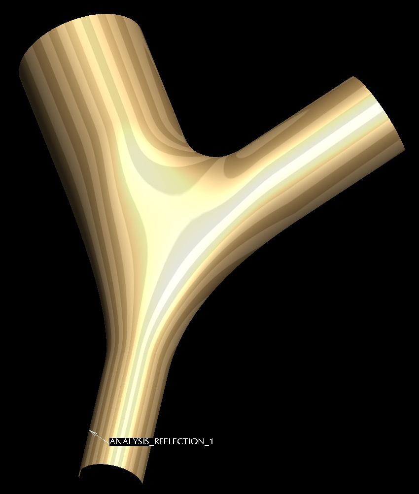
You could piece together an n-sided mesh to do what Antonius showed, basically like this:
- Mark as New
- Bookmark
- Subscribe
- Mute
- Subscribe to RSS Feed
- Permalink
- Notify Moderator
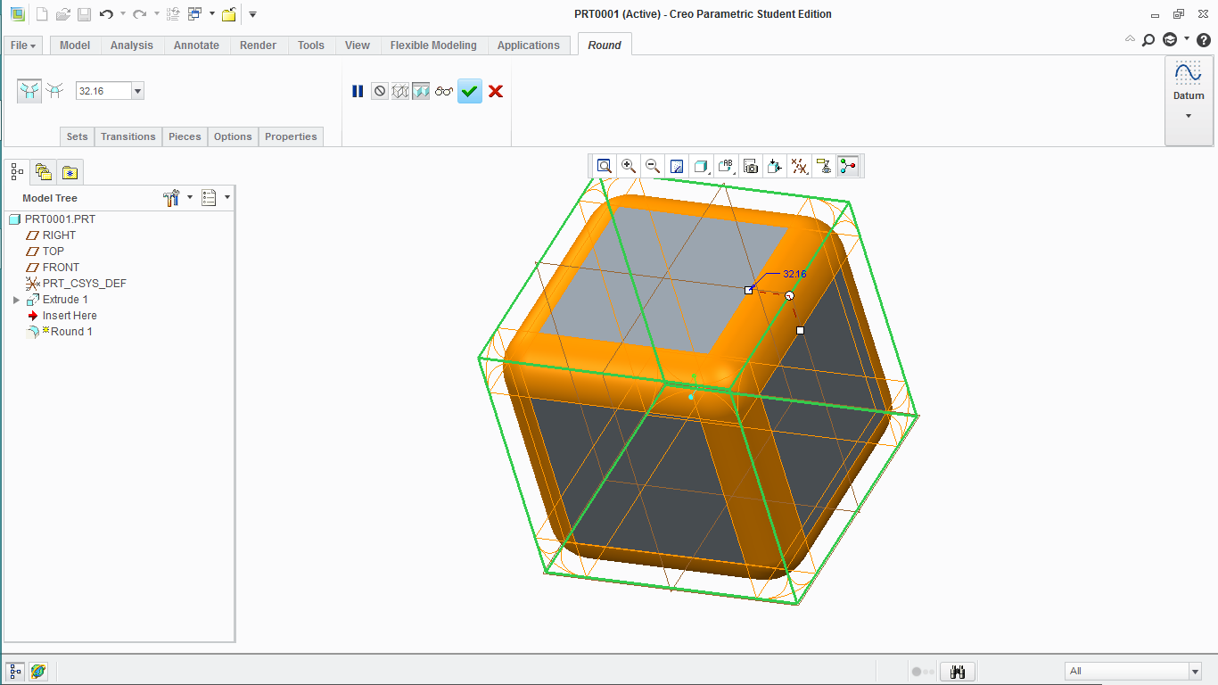
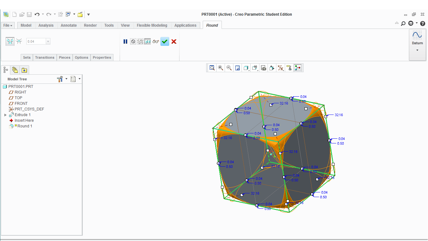
Two step solution,
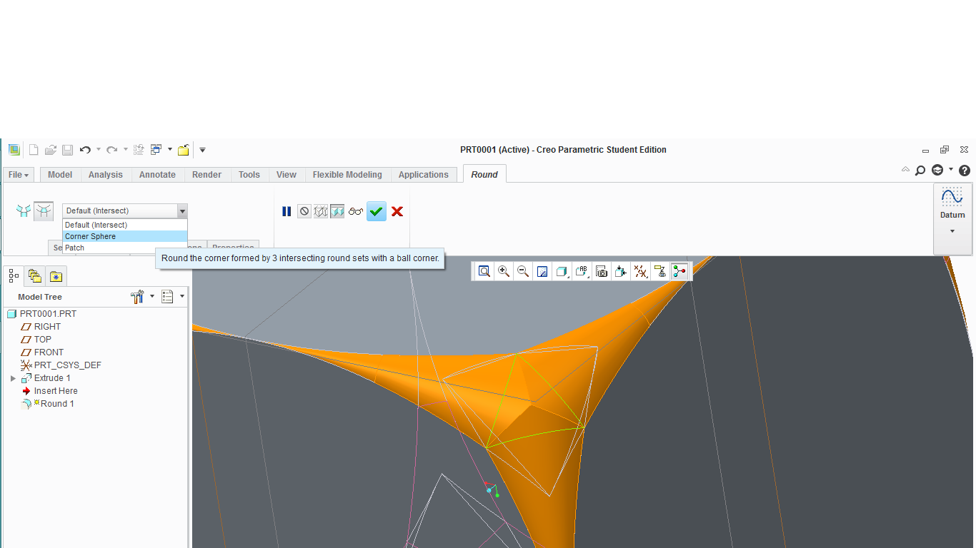
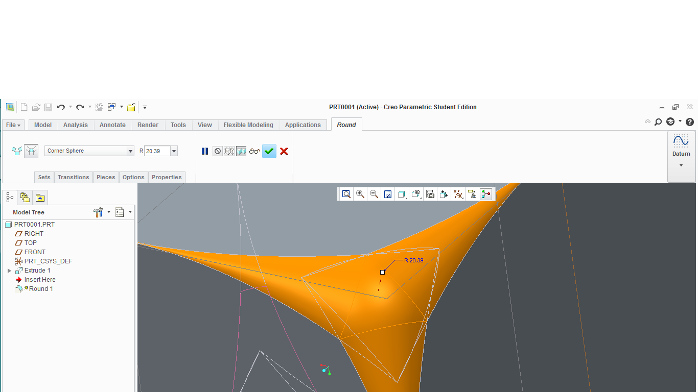
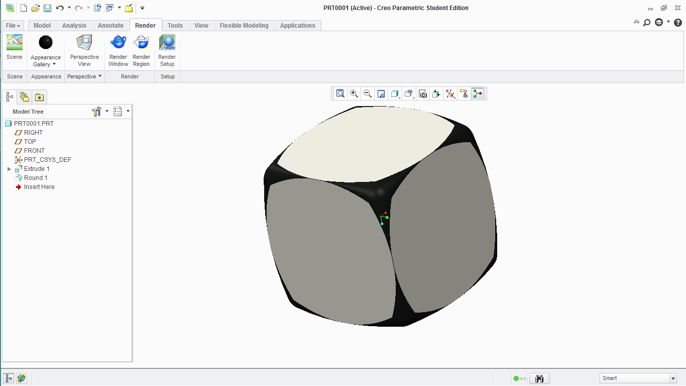
Use a variable round and use the add radius option and place these points between the corners, now give them a tiny value. Next, you can use the corner sphere transition and that's it.
The model was created in Creo Parametric 2.0 Student Version, sorry for that.
Look this dice.
- Mark as New
- Bookmark
- Subscribe
- Mute
- Subscribe to RSS Feed
- Permalink
- Notify Moderator
I am reading this thread for the first time and wondering what the final geometry turned out like? In other words, it seems like every solution more or less fit the description of "belt sanding a corner".
- Mark as New
- Bookmark
- Subscribe
- Mute
- Subscribe to RSS Feed
- Permalink
- Notify Moderator
I think the result is that we -really- need a Sandpaper/Rasp/Grinder feature ![]()
- Mark as New
- Bookmark
- Subscribe
- Mute
- Subscribe to RSS Feed
- Permalink
- Notify Moderator
We did it with a chamfer, then radiused the edges of the chamfer to simulate the blending.
I have attached a video from another CAD system that shows how easy it really SHOULD be!!!
- Mark as New
- Bookmark
- Subscribe
- Mute
- Subscribe to RSS Feed
- Permalink
- Notify Moderator
I don't know if this is just a graphical anomaly, but it looks like it's not tangent (unless that's okay)
- Mark as New
- Bookmark
- Subscribe
- Mute
- Subscribe to RSS Feed
- Permalink
- Notify Moderator
Yep, that is the boundary blend version with a solidify like the video I posted above.
Creo's boundary blend is seriously lacking in patching up a simple closed boundary such as this.
- Mark as New
- Bookmark
- Subscribe
- Mute
- Subscribe to RSS Feed
- Permalink
- Notify Moderator
That tool in NX is cool, but at the same time, it seems to be a semi-random result in shape.

