
Turn on suggestions
Auto-suggest helps you quickly narrow down your search results by suggesting possible matches as you type.
Showing results for
Turn on suggestions
Auto-suggest helps you quickly narrow down your search results by suggesting possible matches as you type.
Showing results for
Community Tip - Did you get called away in the middle of writing a post? Don't worry you can find your unfinished post later in the Drafts section of your profile page. X
- Community
- Creo+ and Creo Parametric
- Creo Parametric Tips
- Did You Know? Tips and Tricks for Cable Design in ...
Options
- Subscribe to RSS Feed
- Mark as New
- Mark as Read
- Bookmark
- Subscribe
- Printer Friendly Page
- Notify Moderator
Did You Know? Tips and Tricks for Cable Design in PTC Creo Parametric Piping and Cabling Extension
No ratings
Our weekly Did You Know series focuses on providing users with informative, “how-to” tips to help them get the most out of PTC Creo. This week’s post, provided by Product Management Director Jim Barrett-Smith, is a brief, introductory overview of routing cables inside the PTC Creo Parametric Piping and Cabling Extension. Users will learn how to filter logical cables, add locations to axis, and understand how the next location in a wire segment will be created.
Tip 1: Filtering Logical Cables
First, select Route Cables under the Cabling section of the user interface. In the Route Cables dialog you will notice there is a Find tool. This will find all the wires and cables with logical references. If this is a very large list, you can refine it by simply selecting a designated component from the graphics area. When you select a designated component, the wires that attach to it are added to the Route Cables dialog. If you hold control and left click, you can select multiple components
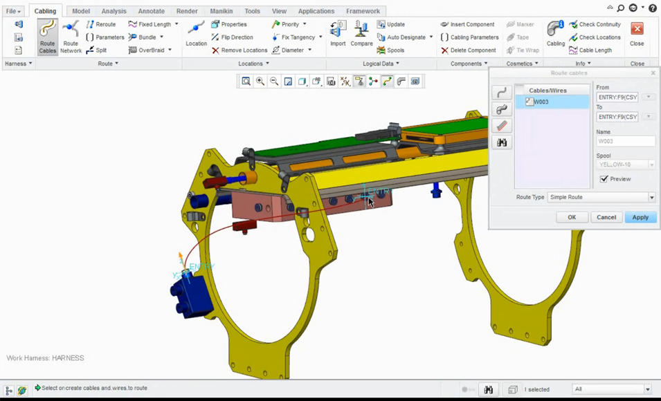
When selecting individual components, the wires which attach to them are automatically added to the Route cables dialog
Tip 2: Adding Locations to an Axis
After you place your simple route, you can start adding locations. In Pro/ENGINEER Wildfire 4.0, the system would automatically place a location onto each end of the axis. If the axis was very short, the cable would form loops in order to satisfy the minimum bend radius.
In PTC Creo, the default behavior is to add a location on the axis at the selection point. If you want the old Pro/ENGINEER Wildfire 4.0 behavior you can right click and choose Along or you can change the configuration option default_cable_axis_location from On to Along and the system will then place a location at each end of the axis. Note: The configuration option is from PTC Creo 2.0 M090 onwards.
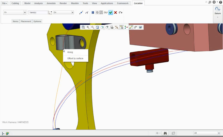
When adding locations to an axis, you can revert back to the old Pro/ENGINEER Wildfire 4.0 behavior by right clicking and selecting Along. This places locations at each end of the axis.
Tip 3: Choosing Next Locations
When you’re adding locations, take notice that half of the wire is orange while the other half is red. The red segments are where you’re going to add your next location. When you choose the next location and click, you’ll see that it has been added in the red segment. If you want to add a location in the orange segment then simply choose Reverse Direction from Location tab.
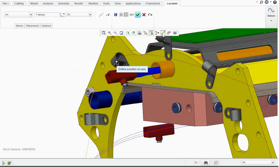 When choosing your next location, follow the red segments. When you choose the next location and click, it will be added to the red segment.
Check out our video tutorial on the PTC University Learning Exchange (“Cabling Design Routing Cables Tips and Tricks”) to see this advice in action. We’d also love to hear your suggestions for working with cables in PTC Creo Parametric Piping and Cabling.
For more in-depth product feature explanations, visit our Tech Tips area.
Have some ideas about what PTC Creo product features you’d like to learn more about? Send me a message or leave a comment below and we’ll write up the best ideas from the community. Thanks for reading, looking forward to all of your feedback!
In case you missed it, here are our recent Did You Know posts:
1) Creating Helical Sweeps for Springs
