Turn on suggestions
Auto-suggest helps you quickly narrow down your search results by suggesting possible matches as you type.
Showing results for
Turn on suggestions
Auto-suggest helps you quickly narrow down your search results by suggesting possible matches as you type.
Showing results for
Community Tip - Did you get an answer that solved your problem? Please mark it as an Accepted Solution so others with the same problem can find the answer easily. X
- Community
- Creo+ and Creo Parametric
- 3D Part & Assembly Design
- Re: Force loading convergence problem
Options
- Subscribe to RSS Feed
- Mark Topic as New
- Mark Topic as Read
- Float this Topic for Current User
- Bookmark
- Subscribe
- Mute
- Printer Friendly Page
Force loading convergence problem
Feb 27, 2017
08:37 AM
- Mark as New
- Bookmark
- Subscribe
- Mute
- Subscribe to RSS Feed
- Permalink
- Notify Moderator
Feb 27, 2017
08:37 AM
Force loading convergence problem
Hello,
I have a task, see attached picture. There is a simple spring loaded by a force on the top. If the spring is attached by the force directly on top then the convergence is OK. (See Case 1). If the force attaches the top red body (Case 2) then already the step 2 is not able to converge. If I define a displacement instead of force then the convergence is OK for both cases.
My interface type is Contact, and I used linear material model.
What do you think? What is the problem with the force loading on the top body?
Thanks
Roland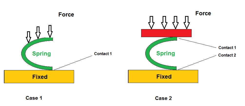
Labels:
- Labels:
-
Data Exchange
9 REPLIES 9
Feb 27, 2017
09:44 AM
- Mark as New
- Bookmark
- Subscribe
- Mute
- Subscribe to RSS Feed
- Permalink
- Notify Moderator
Feb 27, 2017
09:44 AM
Is the red body constrained by anything other than the contact with the spring?
Is it sufficiently stable, or is it liable to tip over under the applied force? Is there anything which will stop it tipping over?
Feb 27, 2017
09:48 AM
- Mark as New
- Bookmark
- Subscribe
- Mute
- Subscribe to RSS Feed
- Permalink
- Notify Moderator
Feb 27, 2017
09:48 AM
Roland,
example as test
(without large deformation).
regards
paul
Feb 28, 2017
03:07 AM
- Mark as New
- Bookmark
- Subscribe
- Mute
- Subscribe to RSS Feed
- Permalink
- Notify Moderator
Feb 28, 2017
04:52 AM
- Mark as New
- Bookmark
- Subscribe
- Mute
- Subscribe to RSS Feed
- Permalink
- Notify Moderator
Feb 28, 2017
04:52 AM
Hello Jonathan and Paul,
thanks a lot. You are absolutely right. I did not fix the direction of top body. I corrected it already.
I checked Paul's test model. I detected that the red edges are fixed in direction X. By this way, the spring will deform only but it is able to motion. Am I correct?
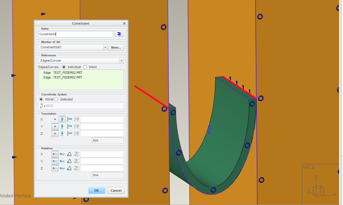
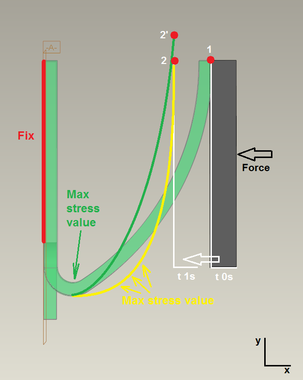
Please check my original geometry below:
The green part will be bended by a force acting on grey part. If the red point is fixed in direction Y - point 1 moves to point 2 - (based on Paul's suggestion) then the yellow deformation will occur. But, if the red point is not fixed then the result shows the green deformation with different stress value. (Point 1 moves to Point 2'). It is evident that the convergence is more stable with the fixed red point but in the real, the green deformation can be seen, I think. The main problem is that this solution will result a slippage and friction force in the red point which continously causes unstable convergence.
What do you think? How can I set the interface to increase the stability of convergence? Larger friction coeff? Or should I define it without friction? Perhaps finer mesh in direction of slippage?
Thanks for your suggestions:
Roland
Feb 28, 2017
08:45 AM
- Mark as New
- Bookmark
- Subscribe
- Mute
- Subscribe to RSS Feed
- Permalink
- Notify Moderator
Feb 28, 2017
08:45 AM
Why not test the model, a) without friction, then b) with infinite friction (equivalent to fixing the end of the spring in X)? These are presumably the bounds of the possible situations; the real situation is likely to be in the middle. You will also see how well each converges.
If you then c) run finite friction, the results will probably depend on the starting conditions, or the movement history: you may get a different answer if you compress it once, or if you then allow it to move back and compress it again.
Feb 28, 2017
09:26 AM
- Mark as New
- Bookmark
- Subscribe
- Mute
- Subscribe to RSS Feed
- Permalink
- Notify Moderator
Feb 28, 2017
09:26 AM
friction is wrong in simulate.
example 2 (penetration).
regards
Paul
Feb 28, 2017
12:52 PM
- Mark as New
- Bookmark
- Subscribe
- Mute
- Subscribe to RSS Feed
- Permalink
- Notify Moderator
Feb 28, 2017
12:52 PM
Hello Roland,.
Why do you have all these restrictions of symmetry?
The room downstairs is constrained in one direction?
I don't know if this is done on purpose not knowing everything about your system.
Kind regards.
Denis
Mar 01, 2017
06:55 AM
- Mark as New
- Bookmark
- Subscribe
- Mute
- Subscribe to RSS Feed
- Permalink
- Notify Moderator
Mar 01, 2017
06:55 AM
Yes, it is a real problem of course. The green part (in my previous comment) is the original spring.
OK, thanks your suggestions and the pdf file. I dont know that the "contact with finite friction" solution includes errors.
Finally, I fixed the red point in direction Y, and red fix support line (left side) also can move in the same direction. (I think, the final result is same to the green deformed spline in terms of deformation and stress.) Now the convergence is ok and there is not slippage during the full process.
But I have an interesting question. Why can it not be defined "Contact" interface type for a simple (linear) static analysis? In this case, the software sets it to "Free" automatically. What is the reason? (Sorry for the beginner questions)
Thanks a lot;
Roland
Mar 06, 2017
03:45 PM
- Mark as New
- Bookmark
- Subscribe
- Mute
- Subscribe to RSS Feed
- Permalink
- Notify Moderator
Mar 06, 2017
03:45 PM
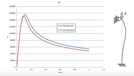
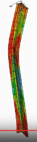
I have not read all posts above, but if your structure "collapses" in the sense that its stiffness first increases and then decreases, your analysis will not converge with a continously increasing load. It can't. You will have to apply you load using an enforced displacement, as I did here in this plastic collapse analysis. The displacement was prescribed, the force was detected using a reaction load measure. You will reach the critical collapse load, and then the structure's response will be weakening; the force required to continue to deform the structure drops once you are past the critical collapse load.
Here is my complete presentation, unfortunately in swedish... Nya elementtyper i Creo Simulate - YouTube
I created this presentation as Creo Simulate promotion some years ago while working for a ptc reseller in Sweden/Norway.