
Turn on suggestions
Auto-suggest helps you quickly narrow down your search results by suggesting possible matches as you type.
Showing results for
Turn on suggestions
Auto-suggest helps you quickly narrow down your search results by suggesting possible matches as you type.
Showing results for
- Community
- Creo+ and Creo Parametric
- 3D Part & Assembly Design
- Plate bending
Options
- Subscribe to RSS Feed
- Mark Topic as New
- Mark Topic as Read
- Float this Topic for Current User
- Bookmark
- Subscribe
- Mute
- Printer Friendly Page
Plate bending
Mar 31, 2017
08:58 AM
- Mark as New
- Bookmark
- Subscribe
- Mute
- Subscribe to RSS Feed
- Permalink
- Notify Moderator
Mar 31, 2017
08:58 AM
Plate bending
Hello,
I have a returning problem. I often have to simulate the process of different metal plate bending. There are a lot of cases when these processes include more steps. (Bending 1, Bending 2..Bending X). As far as I know, the material will include a residual stress after all bendings (in case of sigma > yield stress). So the result of current bending will depend on the residual stress field generated by previous bending step. Based on this, the simulation (result of STEP 2) will be correct and exact if the STEP 1 also were simulated.
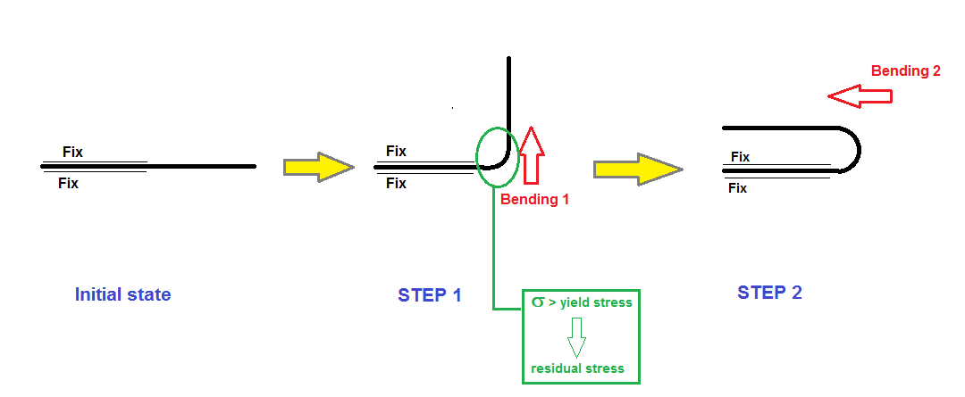
At the moment I prepare the STEP 1 geometry (bended already) in Creo and a simulate only the STEP 2. Consideration of all STEPs would be too complicated and long. But I think this solution is not correct becasue the STEP 2 starts fomr a state which doesn't include the residual stresses.
- How can I consider the residual stress from STEP 1 with more simple method?
- Or how can I separate the STEPs? For example; Analysis 1: STEP 1 only than Analysis 2: STEP 2 only initialized from result of Analysis 1.
Thanks a lot:
Roland
Labels:
- Labels:
-
Data Exchange
20 REPLIES 20
Mar 31, 2017
08:57 PM
- Mark as New
- Bookmark
- Subscribe
- Mute
- Subscribe to RSS Feed
- Permalink
- Notify Moderator
Mar 31, 2017
08:57 PM
sorry
it's not for simulate (mechanica) possible
ANSYS etc
regards
paul
Apr 03, 2017
05:23 AM
- Mark as New
- Bookmark
- Subscribe
- Mute
- Subscribe to RSS Feed
- Permalink
- Notify Moderator
Apr 03, 2017
05:26 AM
- Mark as New
- Bookmark
- Subscribe
- Mute
- Subscribe to RSS Feed
- Permalink
- Notify Moderator
Apr 03, 2017
05:26 AM
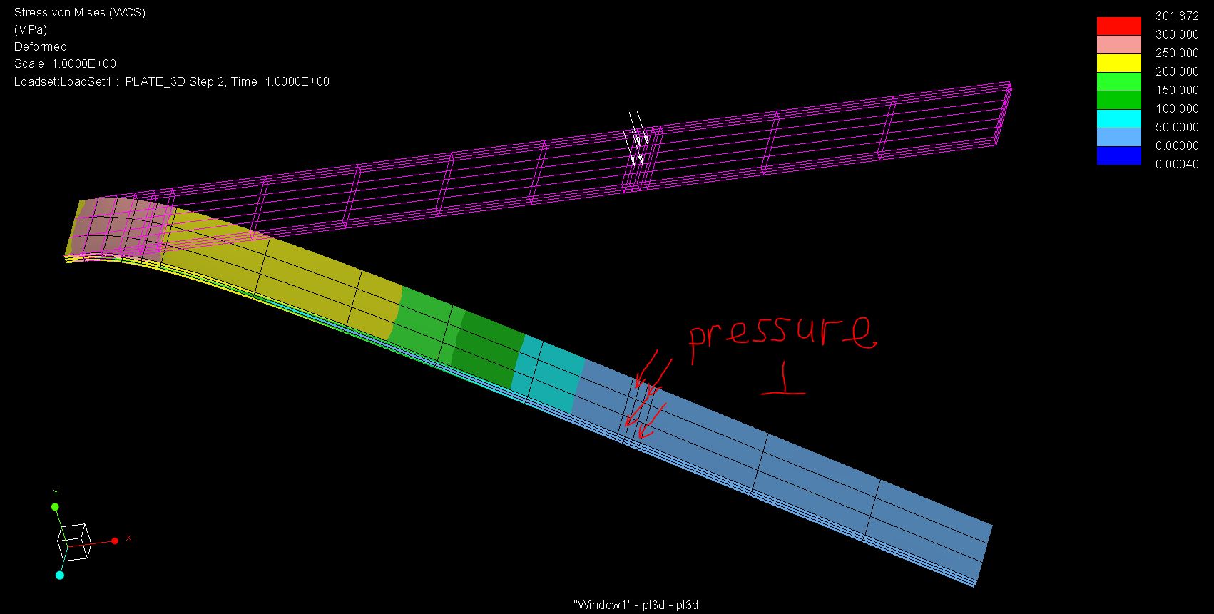
color plot:
Apr 03, 2017
07:42 AM
- Mark as New
- Bookmark
- Subscribe
- Mute
- Subscribe to RSS Feed
- Permalink
- Notify Moderator
Apr 03, 2017
07:42 AM
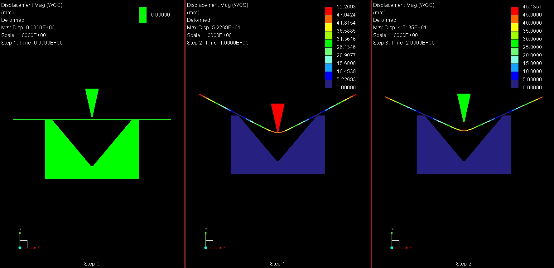
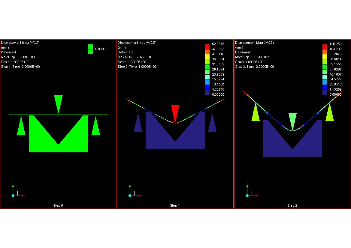
Hello Paul,
it is OK but in your case, the STEP 2 is the bending tool back. In my case, an other tool (from other direction) should bend - initialized from the STEP 1.
Actually, it is possible to define the STEP 1 and 2 together in one analysis but the full simulation with 2 (or more) STEPs is too complicated. It would be easier if one simulation case includes one bending process. In addition, if the STEP x diverges then the STEP x-1 should not be started again...
Apr 03, 2017
10:20 AM
- Mark as New
- Bookmark
- Subscribe
- Mute
- Subscribe to RSS Feed
- Permalink
- Notify Moderator
Apr 04, 2017
02:09 PM
- Mark as New
- Bookmark
- Subscribe
- Mute
- Subscribe to RSS Feed
- Permalink
- Notify Moderator
Apr 04, 2017
02:09 PM
Hello Paul,
Thanks for this very interesting example.
I have downloaded your files and run.
The lifters move well but the plate remains horizontal.
I've probably missed something?
Kind regards.
Denis
Apr 04, 2017
10:47 PM
- Mark as New
- Bookmark
- Subscribe
- Mute
- Subscribe to RSS Feed
- Permalink
- Notify Moderator
Apr 04, 2017
10:47 PM
Hello Denis,
curious.
I use Creo Simulate 2.0 M080,
standard settings only (with the ecxeption of Fatigue Advisor).
regards
paul
Apr 05, 2017
12:57 AM
- Mark as New
- Bookmark
- Subscribe
- Mute
- Subscribe to RSS Feed
- Permalink
- Notify Moderator
Apr 05, 2017
03:45 AM
- Mark as New
- Bookmark
- Subscribe
- Mute
- Subscribe to RSS Feed
- Permalink
- Notify Moderator
Apr 05, 2017
03:45 AM
Hello Denis,
based on my checking, Paul's test model is OK but the time step is too large in "Number of Master Steps".
After decreasing of time step it will operate well I think.
Regerds
Roland
Apr 05, 2017
09:33 AM
- Mark as New
- Bookmark
- Subscribe
- Mute
- Subscribe to RSS Feed
- Permalink
- Notify Moderator
Apr 05, 2017
09:33 AM
Hello Paul, Hello Roland,.
Thanks for your answers, I'll look at that in a moment.
Kind regards.
Denis
Apr 05, 2017
09:51 AM
- Mark as New
- Bookmark
- Subscribe
- Mute
- Subscribe to RSS Feed
- Permalink
- Notify Moderator
Apr 28, 2017
08:40 AM
- Mark as New
- Bookmark
- Subscribe
- Mute
- Subscribe to RSS Feed
- Permalink
- Notify Moderator
Apr 05, 2017
10:31 AM
- Mark as New
- Bookmark
- Subscribe
- Mute
- Subscribe to RSS Feed
- Permalink
- Notify Moderator
Apr 05, 2017
10:31 AM
The process of bending in the industry is basically a forming process where a sheet material is put within a die and then the upper side is pressed so that it can be bent well. This design step for bending has made easy operations as compared to Catia & Autocad..I loved the schooldays which was not containing anything of this.It was just a pure enjoyment.
May 04, 2017
08:21 AM
- Mark as New
- Bookmark
- Subscribe
- Mute
- Subscribe to RSS Feed
- Permalink
- Notify Moderator
May 04, 2017
08:21 AM
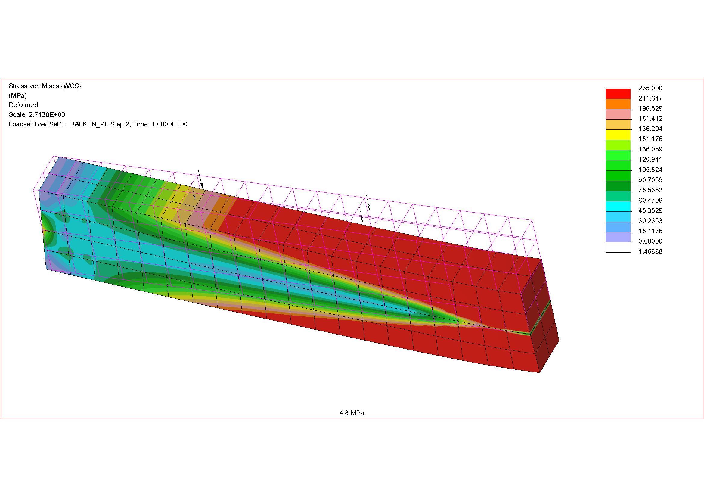
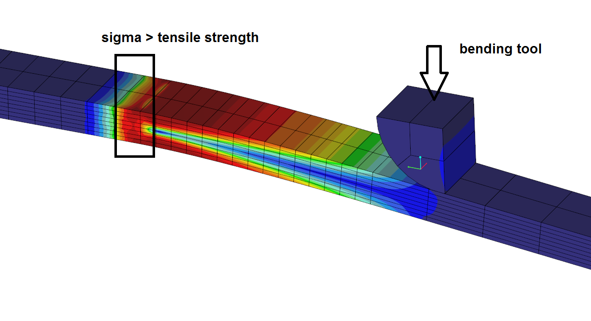
I have created some simulation to investigate the behaviour of material (stress distribution) after the reach of yield stress. (My material model is defined by a measurement)
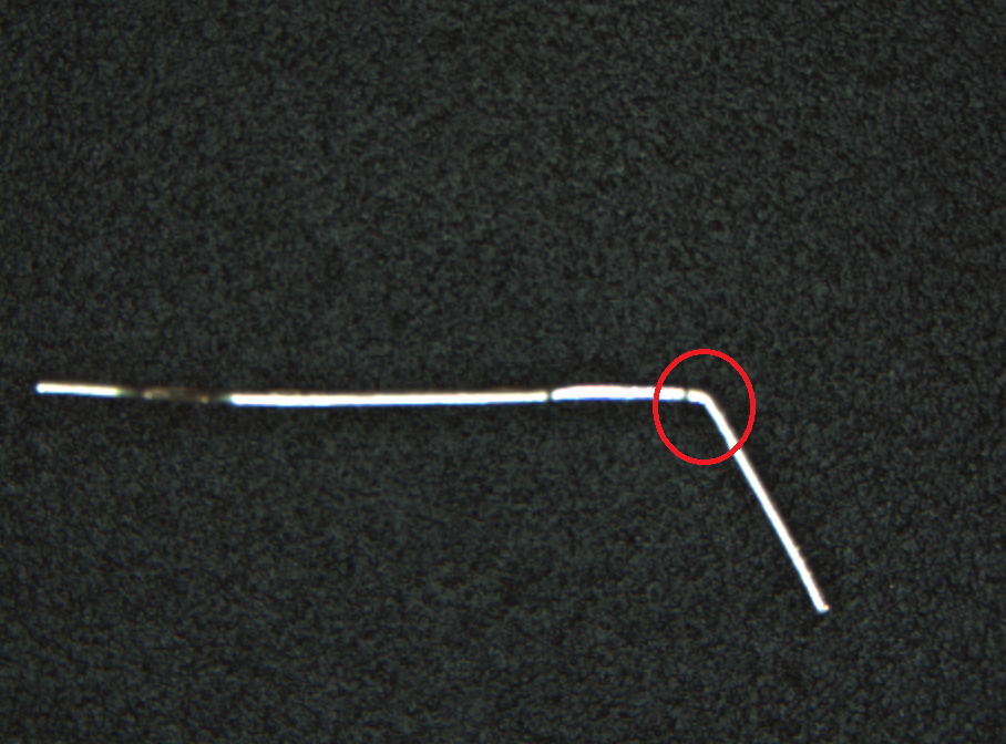
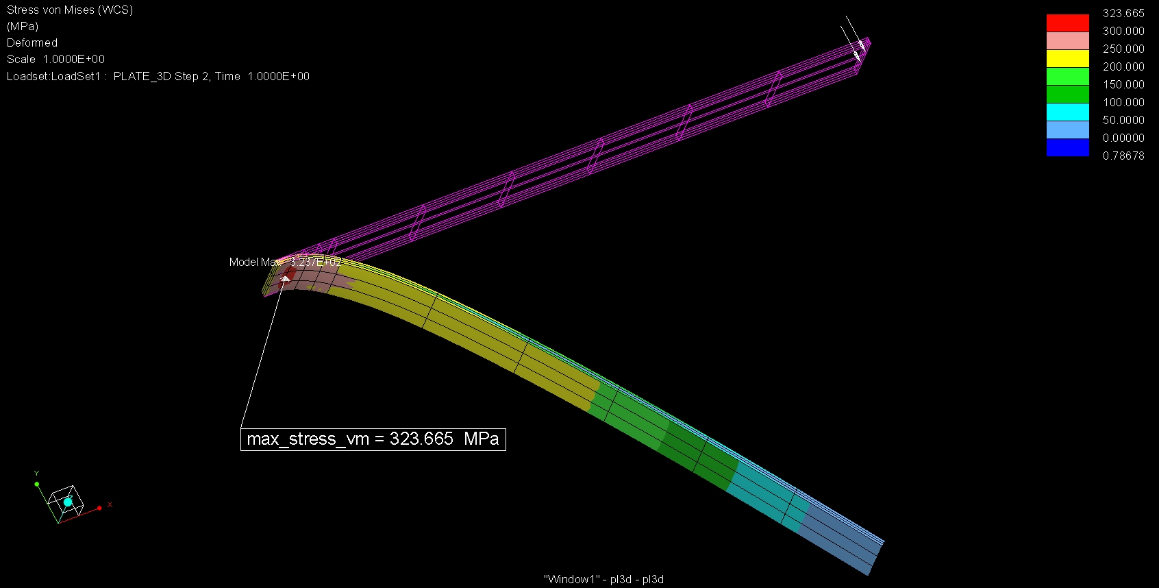
I have a simple measurement with a small part. After the bending of this part, I investiged with microscope the outside surface of part. I see the the material - along the bending radius - reach the yield stress. But the part was not broken...so I think that the stress doesnt reach the tensile stress. Insipte of this, in the simulation, as it can be seen below, the stress is in red area in full cross section along the bending radius....colored by red means stress is over tensile stress.
It seems to me that creo solver estimates over the stress distribution. It shows that the part will break but it did not happen in the course of my measurement.
What is the reason in your opinion?
Thanks
Roland
May 04, 2017
09:17 AM
- Mark as New
- Bookmark
- Subscribe
- Mute
- Subscribe to RSS Feed
- Permalink
- Notify Moderator
May 04, 2017
09:17 AM
hello Roland
i used perfect plasticity:
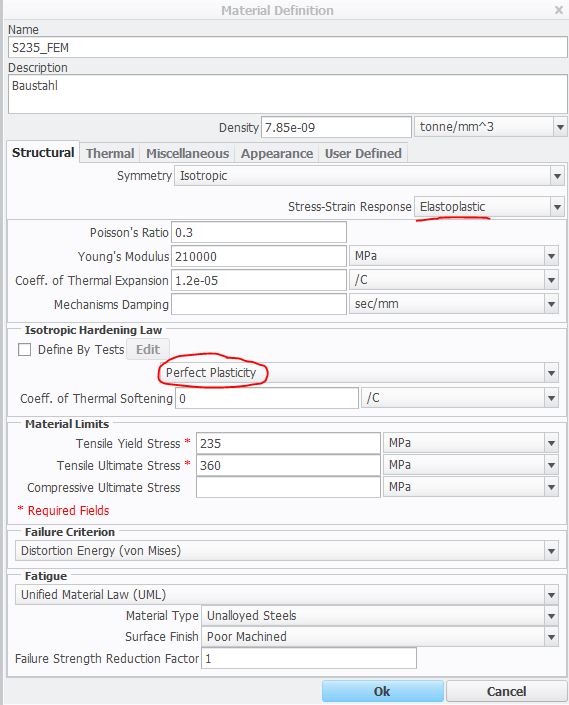
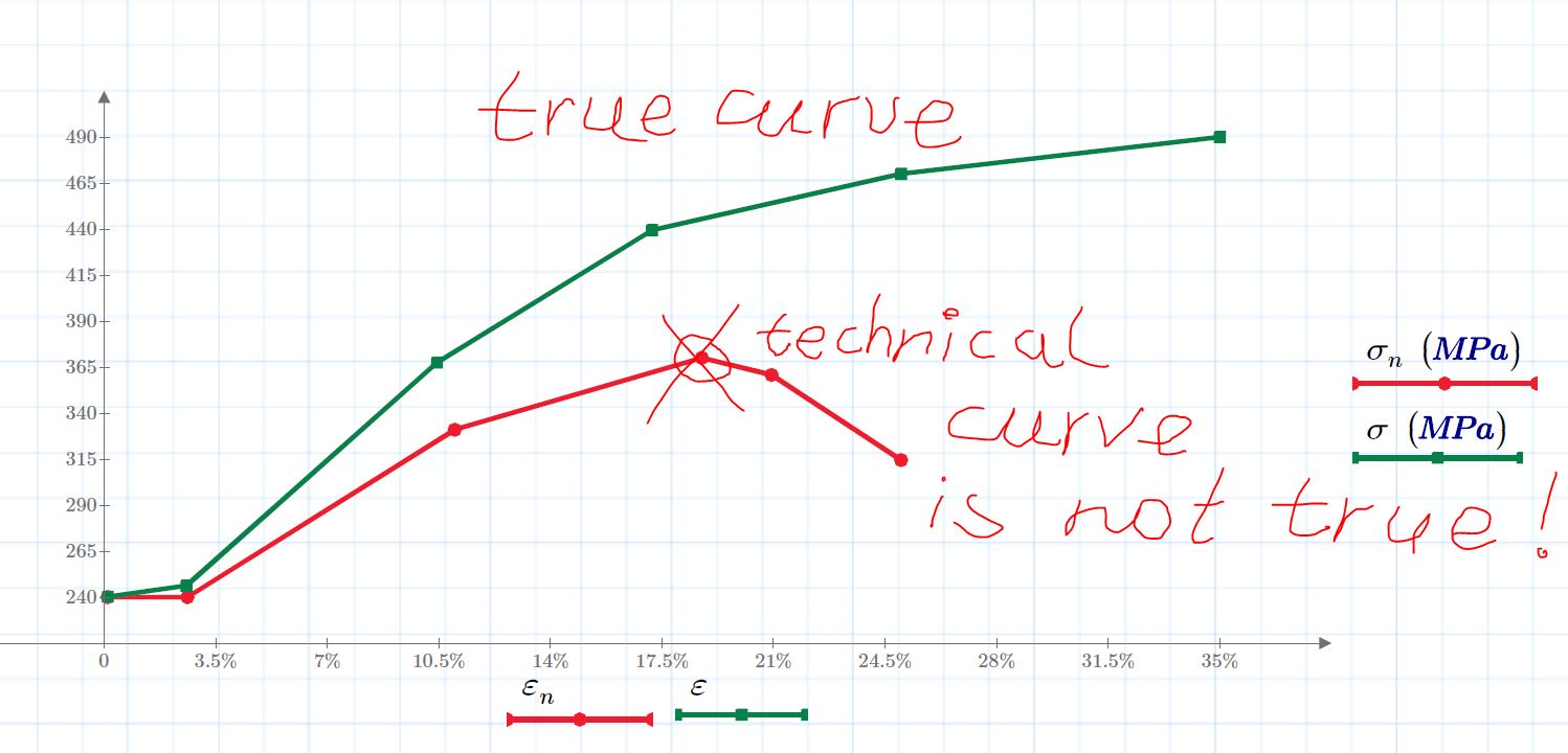
technical curve is not real:
regards
paul
May 05, 2017
03:41 AM
- Mark as New
- Bookmark
- Subscribe
- Mute
- Subscribe to RSS Feed
- Permalink
- Notify Moderator
May 05, 2017
03:41 AM
OK, I tried the perfect plasticity model, the stress value did not reach the ultimate stress, but actually it is not possible caused by the perfect plastisity model:
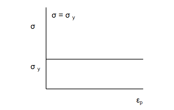
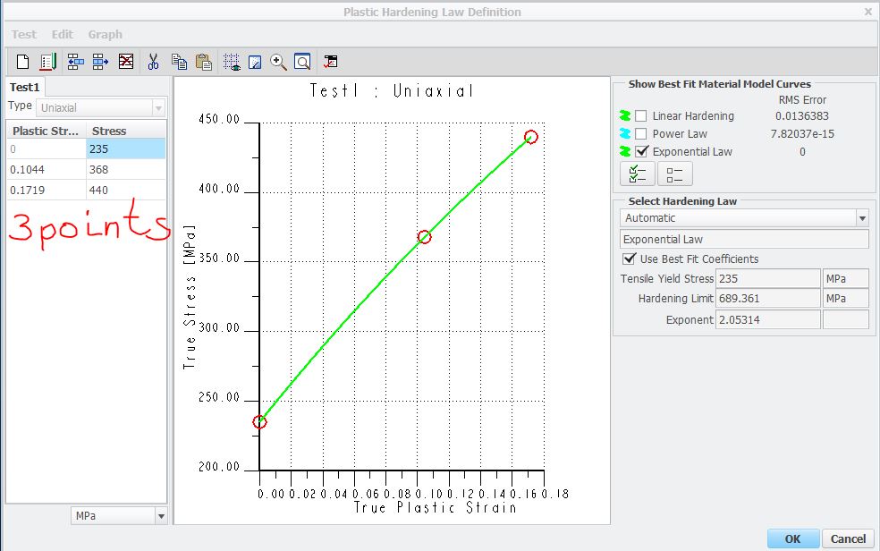
If the stress value is higher than yield stress then it will not increase so it is evident that the stress doesnt reach the ultimate stress... In my opinion, this mode is ok for special materials but in my case it is not ok. I have a measured material curve and it is not similar to the perfect mat. model. The best case was the definition with the exponential law but it leads to too high stress value.... I dont understand it....
May 05, 2017
04:29 AM
- Mark as New
- Bookmark
- Subscribe
- Mute
- Subscribe to RSS Feed
- Permalink
- Notify Moderator
May 05, 2017
04:29 AM
OK, You start so:
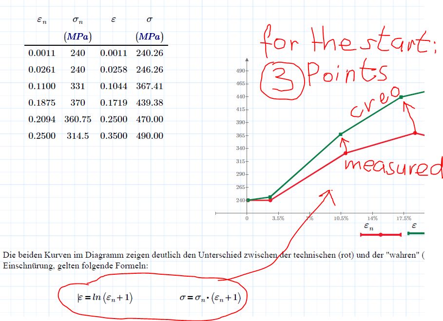
as exponential law:
regards
paul
May 08, 2017
04:52 AM
- Mark as New
- Bookmark
- Subscribe
- Mute
- Subscribe to RSS Feed
- Permalink
- Notify Moderator
May 08, 2017
04:52 AM
Yes it is ok, I understand you. But my problem is; the stress values will be too high after the correct definition of true stress. Based on results, the stress is higher than the ultimate stress while the measurement shows that the test part did not broken after bending. I tried different time steps and mesh refinement but a result is almost same...
THe picture shows the real part after bending. The deformation is plastic but there is no breakage. In the simulation, the stress value reach the ultimate stress in red area...in full cross section. I dont understand the reason....
May 08, 2017
10:32 AM
- Mark as New
- Bookmark
- Subscribe
- Mute
- Subscribe to RSS Feed
- Permalink
- Notify Moderator
May 08, 2017
10:32 AM
Roland,
a little example V3 (contact-constraints)
regards
paul
May 09, 2017
07:55 AM
- Mark as New
- Bookmark
- Subscribe
- Mute
- Subscribe to RSS Feed
- Permalink
- Notify Moderator
