
Turn on suggestions
Auto-suggest helps you quickly narrow down your search results by suggesting possible matches as you type.
Showing results for
Turn on suggestions
Auto-suggest helps you quickly narrow down your search results by suggesting possible matches as you type.
Showing results for
Community Tip - Want the oppurtunity to discuss enhancements to PTC products? Join a working group! X
- Community
- Creo+ and Creo Parametric
- 3D Part & Assembly Design
- Re: Problem importing STEP
Options
- Subscribe to RSS Feed
- Mark Topic as New
- Mark Topic as Read
- Float this Topic for Current User
- Bookmark
- Subscribe
- Mute
- Printer Friendly Page
Problem importing STEP
Nov 14, 2016
05:12 AM
- Mark as New
- Bookmark
- Subscribe
- Mute
- Subscribe to RSS Feed
- Permalink
- Notify Moderator
Nov 14, 2016
05:12 AM
Problem importing STEP
Hi,
I’m trying to import a Cylinder ( 2 parts, Tube and Rod) into Creo 3.0. Problem is that it will not generate a Solid of it, when I try the same into Autodesk Inventor, it makes it a Solid no problem. Been trying Import Doctor, but not much Luck with model so far.
Anyone who have some good tips on how to do this?
Adding problematic Cylinders:
This thread is inactive and closed by the PTC Community Management Team. If you would like to provide a reply and re-open this thread, please notify the moderator and reference the thread. You may also use "Start a topic" button to ask a new question. Please be sure to include what version of the PTC product you are using so another community member knowledgeable about your version may be able to assist.
Labels:
- Labels:
-
Data Exchange
13 REPLIES 13
Nov 14, 2016
09:51 AM
- Mark as New
- Bookmark
- Subscribe
- Mute
- Subscribe to RSS Feed
- Permalink
- Notify Moderator
Nov 14, 2016
09:51 AM
Thanks for reply, will try again now, and post screenshot of problem-area.
Nov 14, 2016
12:51 PM
- Mark as New
- Bookmark
- Subscribe
- Mute
- Subscribe to RSS Feed
- Permalink
- Notify Moderator
Nov 14, 2016
12:51 PM
I worked 5 years with Inventor, and rarely had problems that I can remember with importing *.step files. Though I have tried to Save As from Inventor, to several other 3D formats, and then import to Creo, without any luck. Been looking at youtube for tips as well, but no luck so far. I have also talked to the Company who made the Cylinders, and they tested to import again, with no problems, but then again, they use Inventor, so it might be something there.
Nov 14, 2016
10:04 AM
- Mark as New
- Bookmark
- Subscribe
- Mute
- Subscribe to RSS Feed
- Permalink
- Notify Moderator
Nov 14, 2016
10:04 AM
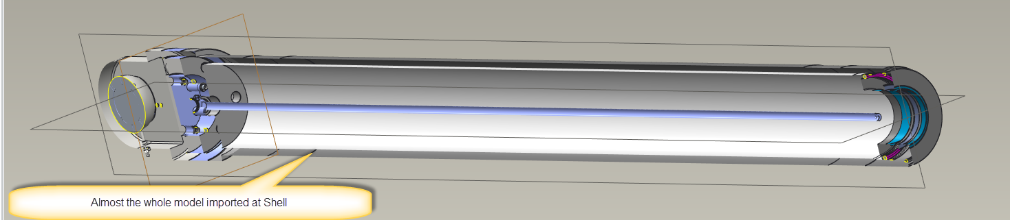
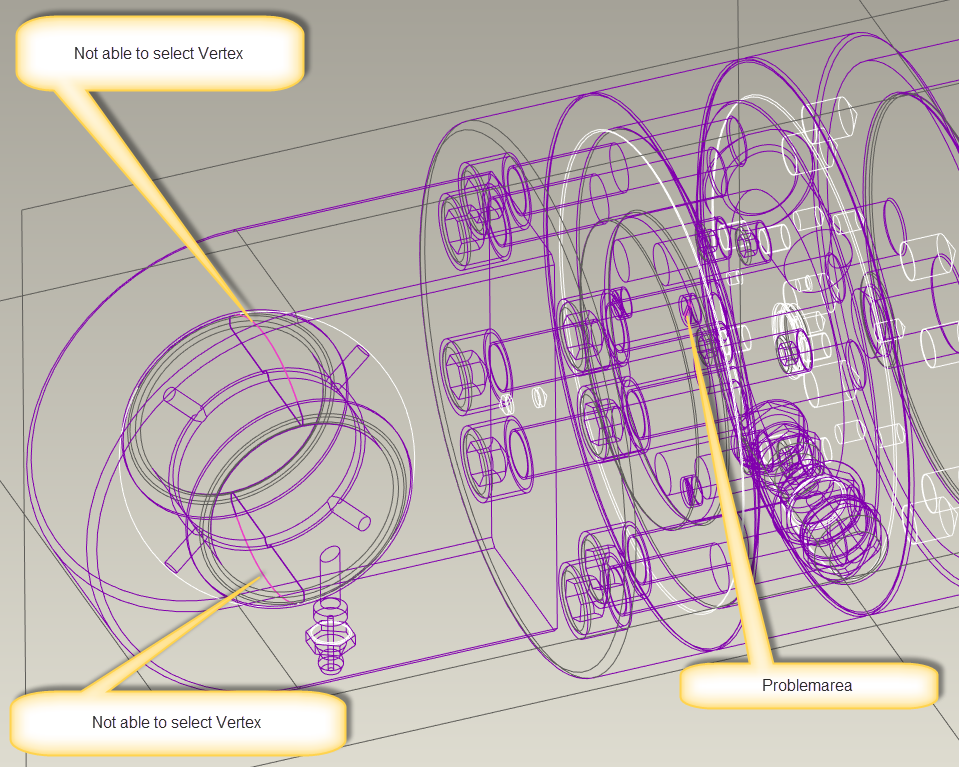
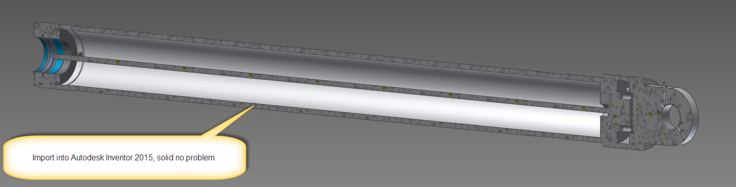
Here are 3 Pictures. 2 from Creo 3.0 and one from Autodesk Inventor 2015. Used the same model to import in both CAD's, easy pie in Inventor, but not so in Creo. Most of the model come in as Shell.
Nov 14, 2016
01:38 PM
- Mark as New
- Bookmark
- Subscribe
- Mute
- Subscribe to RSS Feed
- Permalink
- Notify Moderator
Nov 14, 2016
01:38 PM
Hi,
in 88965-Rod-rev1.step.zip there is STEP file representing an assembly. Unfortunately it is imported into Creo as PART, by default. This means that STEP files does not contain information about assembly components. Therefore Creo is not able to import it properly.
MH
Martin Hanák
Nov 14, 2016
02:54 PM
- Mark as New
- Bookmark
- Subscribe
- Mute
- Subscribe to RSS Feed
- Permalink
- Notify Moderator
Nov 14, 2016
02:54 PM
Hi, and thanks for reply.
I was not aware of that.
Nov 14, 2016
02:26 PM
- Mark as New
- Bookmark
- Subscribe
- Mute
- Subscribe to RSS Feed
- Permalink
- Notify Moderator
Nov 14, 2016
02:26 PM
I have heard that the data made with PTC export tools gives other CAD users headaches.
Here the case is that STEP file is not imported correctly - also not unheard of...
I'm pretty sure you can use the import data doctor to fix up the problems - for included example - I've managed to solidify the cylinder rod.
My general method is to remove the "bad" geometry / components. But this is painstaking work that leads to modifying the original geometry and does not solve the root issue.
For your files, though, it's curious that Creo tries to bring them in as parts - they are clearly assemblies. Is there a setting in inventor that you can use to manipulate this aspect?
You can also try to remove the problem components prior to exporting the Inventor file. For example - it seems like it's the spherical bearing that's giving creo troubles; If you remove that part out of the Inventor assembly prior to generating the step file, does that help you on the Creo end?
Nov 14, 2016
03:04 PM
- Mark as New
- Bookmark
- Subscribe
- Mute
- Subscribe to RSS Feed
- Permalink
- Notify Moderator
Nov 14, 2016
03:04 PM
Hi, and thanks for reply.
I can check with the Cylinder-manufacturer to see if I can get the original Inventor-assembly packed, but it usually takes a bit of time to get a response, and this project, as always, need to be done asap.
To repair the Geometry is quite painstaking, and not to straight forward, as I have not used that tool before, but I’ll try to see what I can make of it.
I for first did not think this would become a problem, as 3.0, was supposed to just use any format easy pie. First I’ll try to work with the model that got imported correctly into Inventor, to see if I can simplify it some. I’ll write update when I have tested more.
Nov 14, 2016
05:21 PM
- Mark as New
- Bookmark
- Subscribe
- Mute
- Subscribe to RSS Feed
- Permalink
- Notify Moderator
Nov 14, 2016
05:21 PM
Yeah, let them know that their STEP files come in as surfaces not just in Creo - I tried it in OnShape and same thing happened. It well might be that other CAD packages can successfully open their files (can someone with Solidworks try it?), but there is a valid reason to be suspecting that they are generating a non-standard STEP file. Maybe there is a way they can enforce AP203 / AP214 compliance during export...
Nov 14, 2016
05:52 PM
- Mark as New
- Bookmark
- Subscribe
- Mute
- Subscribe to RSS Feed
- Permalink
- Notify Moderator
Nov 14, 2016
05:52 PM
Hi and thanks for reply.
I will contact them tommrow, and tell that this.
Nov 14, 2016
07:18 PM
- Mark as New
- Bookmark
- Subscribe
- Mute
- Subscribe to RSS Feed
- Permalink
- Notify Moderator
Nov 14, 2016
07:18 PM
It only contains surface information, no assembly info. I skimmed and searched the file. It looks like only surface output was chosen. It probably is AP203/AP214 compliant, but that doesn't mean much beyond that it can be interpreted with a compatible interpreter. It could be only points and still be compliant if that's what the originator software is set to output.
It has an entry that suggests "Core Data for Automotive Mechanical Design Process" which is part 214.
ISO-10303-21;
HEADER;
/* Generated by software containing ST-Developer
* from STEP Tools, Inc. (www.steptools.com)
*/
FILE_DESCRIPTION(
/* description */ (''),
/* implementation_level */ '2;1');
FILE_NAME(
/* name */ 'F:\\STEP\\88965-Rod-rev1.step',
/* time_stamp */ '2016-11-11T09:52:57+01:00',
/* author */ ('kik'),
/* organization */ (''),
/* preprocessor_version */ 'ST-DEVELOPER v15.6',
/* originating_system */ 'Autodesk Inventor 2015',
/* authorisation */ '');
...
Nov 14, 2016
07:52 PM
- Mark as New
- Bookmark
- Subscribe
- Mute
- Subscribe to RSS Feed
- Permalink
- Notify Moderator
Nov 14, 2016
07:52 PM
Thanks for the background about AP214 compliance. Learn something everyday.
Still, even if you have a surface-only model, Creo should be able to "solidify" it, no? That's what Inventor seems able to do.
Anyway, there are other things that suggest that PTC's product is lacking in this area - notice how the rod-eyes that have been imported into Creo have a sphere that fills them - that shouldn't be there. OnShape does not do this.
And we had people from Delcam's (now Autodesk) powermill / powershape software do a demo recently and they were on about the files they get from Pro/Engineer users (why is every cylinder split in half?) - and how how easy it is for them to fix the surfaces.
Nov 14, 2016
08:36 PM
- Mark as New
- Bookmark
- Subscribe
- Mute
- Subscribe to RSS Feed
- Permalink
- Notify Moderator
Nov 14, 2016
08:36 PM
Every cylinder (every complete surface of revolution) is split due to decisions about how to represent the models. It makes evaluating the surfaces much simpler by not having to handle revolute surfaces as exceptions to every other solid geometry.
A similar question is why aren't all extruded feature faces continuous? Some CAD systems see them as a single piece, but most don't
Split revolutes is fundamental to the way Creo works, and I expect most CAD systems put a complex wrapper to hide that they do exactly the same thing.
As far as the Spherical surfaces in the STEP file are concerned, see ENTITY advanced_face, which is what is in the example STEP file as seen in the example line:
#4194=CLOSED_SHELL('',(#3942,#3943,#3944,#3945,#3946,#3947,#3948,#3949,
#3950,#3951,#3952,#3953,#3954,#3955,#3956,#3957,#3958,#3959,#3960,#3961,
#3962,#3963,#3964,#3965,#3966,#3967,#3968,#3969,#3970,#3971,#3972,#3973,
#3974,#3975,#3976,#3977,#3978,#3979,#3980,#3981,#3982,#3983,#3984,#3985,
#3986,#3987,#3988,#3989,#3990,#3991,#3992,#3993,#3994,#3995,#3996,#3997,
#3998,#3999,#4000,#4001,#4002,#4003,#4004,#4005,#4006,#4007,#4008,#4009,
#4010,#4011,#4012,#4013,#4014,#4015,#4016,#4017,#4018,#4019,#4020,#4021,
#4022,#4023,#4024,#4025,#4026,#4027,#4028,#4029,#4030,#4031,#4032,#4033,
#4034,#4035,#4036,#4037,#4038,#4039,#4040,#4041,#4042,#4043,#4044,#4045,
#4046,#4047,#4048,#4049,#4050,#4051,#4052,#4053,#4054,#4055,#4056,#4057,
#4058,#4059,#4060,#4061,#4062,#4063,#4064,#4065,#4066,#4067,#4068,#4069,
#4070,#4071,#4072,#4073,#4074,#4075,#4076,#4077,#4078,#4079,#4080,#4081,
#4082,#4083,#4084,#4085,#4086,#4087,#4088,#4089,#4090,#4091,#4092,#4093,
#4094,#4095,#4096,#4097,#4098,#4099,#4100,#4101,#4102,#4103,#4104,#4105,
#4106,#4107,#4108,#4109,#4110,#4111,#4112,#4113,#4114,#4115,#4116,#4117,
#4118,#4119,#4120,#4121,#4122,#4123,#4124,#4125,#4126,#4127,#4128,#4129,
#4130,#4131,#4132,#4133,#4134,#4135,#4136,#4137,#4138,#4139,#4140)); which (in part) references #4020
#4020=ADVANCED_FACE('',(#867),#14,.F.); which references
#14=SPHERICAL_SURFACE('',#4419,5.); which references
#4419=AXIS2_PLACEMENT_3D('',#7472,#5226,#5227); and so on.
So the question is whether this STEP file is correct and PTC is generating incorrect geometry or that the STEP file is wrong and other CAD software is ignoring the error. I expect it is the latter case, but I'd have to, by hand, evaluate a large amount of the STEP file to be certain as the ".F." says it has the opposite sense to the #867 surface, and so on. It looks to be about 10 references deep and 1-4 branches per reference, so the PTC STEP expert will have to research it, because that guy will have actual tools to trace how the file is evaluated.
Nov 15, 2016
04:09 AM
- Mark as New
- Bookmark
- Subscribe
- Mute
- Subscribe to RSS Feed
- Permalink
- Notify Moderator
Nov 15, 2016
04:09 AM
Thanks for your effort and time.
I don't need my model to be 100% accurate, but it would be nice to have it as a solid. I have asked the manufacturer, to send me their files as "Pack and Go". If they are willing to do that, I can simplify the model, and try to export it myself, or at least test diffrent variants.
