
Turn on suggestions
Auto-suggest helps you quickly narrow down your search results by suggesting possible matches as you type.
Showing results for
Turn on suggestions
Auto-suggest helps you quickly narrow down your search results by suggesting possible matches as you type.
Showing results for
Community Tip - New to the community? Learn how to post a question and get help from PTC and industry experts! X
- Community
- Creo+ and Creo Parametric
- 3D Part & Assembly Design
- Project Lightning Wish List
Options
- Subscribe to RSS Feed
- Mark Topic as New
- Mark Topic as Read
- Float this Topic for Current User
- Bookmark
- Subscribe
- Mute
- Printer Friendly Page
Project Lightning Wish List
Sep 07, 2010
11:32 AM
- Mark as New
- Bookmark
- Subscribe
- Mute
- Subscribe to RSS Feed
- Permalink
- Notify Moderator
Sep 07, 2010
11:32 AM
Project Lightning Wish List
This list is to articulate our wants and needs to PTC on what changes we would like to see to Pro/Engineer Wildfire with the release of Project Lightning. I was asked to put a list of what my company wanted to see in Lightning, and thought it would be better if PTC saw what the whole Pro/E community wanted to see.
Please keep all comment upbeat and positive. Absolutely no hate statements.
I think it is important to have some rules for this, so here is a starter on them. They are subject to change if it proves to be needed.
- One enhancement per reply - this will make it so people can comment directly to that request with additions, elaborations or +1, -1 comments
- Keep the requests specific and precise - consistent UI throughout Pro/E is a great request, but is very broad and might be better stated differently
- No mention of other company branding, names or abbreviations - if you want your request to be listened to don't say Pro/E needs to be like a different tool. I am sure you can find another way of stating or explaining your wish then make it like ..... Siting other PTC products is OK.
- No off topic discussions
- Keep all comments related to the request you are replying to
- When you post a new request, reply to the original post. This will keep all the request at the top level and better to read.
- Add pictures, screenshot, PDF's or other illustrations to help you point.
- Change the title of your post to have a short title for your request.
- Try to make your request fit with WF5 where possible. It would be useless to request something they already did in WF5. (for example: Update the Cabling module)
- The list is not in order of importance. You can put any request in any order.
- etc...
I will start with a couple requests to get the ball rolling. I will keep adding them over time to give opportunity for others to add requests.
This thread is inactive and closed by the PTC Community Management Team. If you would like to provide a reply and re-open this thread, please notify the moderator and reference the thread. You may also use "Start a topic" button to ask a new question. Please be sure to include what version of the PTC product you are using so another community member knowledgeable about your version may be able to assist.
Labels:
- Labels:
-
Data Exchange
82 REPLIES 82
Sep 07, 2010
11:43 AM
- Mark as New
- Bookmark
- Subscribe
- Mute
- Subscribe to RSS Feed
- Permalink
- Notify Moderator
Sep 07, 2010
11:43 AM
The selection filter is a very helpful tool. It would be more helpful and easy to use if the list was in alphabetical order.
Here is the current WF5 order of the list in part mode.
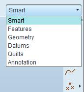
This particular time the list is short, so easier to look through. Sometimes it gets longer and hard to find what you are looking for.
Oct 05, 2010
06:46 AM
- Mark as New
- Bookmark
- Subscribe
- Mute
- Subscribe to RSS Feed
- Permalink
- Notify Moderator
Oct 05, 2010
06:46 AM
It would also be ideal if the map key would pick the filter in every environment.
On wf3 if you have a mapkey filtering for surfaces in the assembly mode the same mapkey would call the filter for vertex in part mode.
Nicolas
Sep 07, 2010
11:48 AM
- Mark as New
- Bookmark
- Subscribe
- Mute
- Subscribe to RSS Feed
- Permalink
- Notify Moderator
Sep 07, 2010
11:48 AM
It would be really nice if Pan, Rotate and Zoom worked the same in all modes of working in Pro/E. For example the way it is now, the holding the middle mouse button in part mode rotates the part. But, if you are in Drawing mode the drawing pans. Scrolling works the same for zoom in both. Panning and Rotating should also. I understand there is no rotate in Drawing mode.
Sep 07, 2010
11:50 AM
- Mark as New
- Bookmark
- Subscribe
- Mute
- Subscribe to RSS Feed
- Permalink
- Notify Moderator
Sep 07, 2010
11:50 AM
Maybe make it so you can Pan, Rotate and Zoom without holding down the modifier key (Ctrl, Alt or Shift). Hold middle mouse to rotate, scroll the wheel to zoom, hold right mouse to pan. Then if you just press and release the middle mouse button without moving the mouse the menu comes up.
Sep 07, 2010
12:32 PM
- Mark as New
- Bookmark
- Subscribe
- Mute
- Subscribe to RSS Feed
- Permalink
- Notify Moderator
Sep 07, 2010
12:32 PM
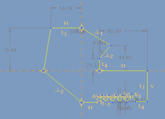
This might be hard to do, but it would be nice if there were an option to set the default zoom on new parts. When you are working on small metric parts it is hard to make the first sketch the right size. It seems to always end up too large. This causes you to have to scale the part and hope eveything moves correctly and you don't have any accidental constrants.
Many of our engineers work on handheld devices, so the internal parts are less than an inch. With the default sketcher zoom it seems that you always end up with 5 or 10 inch parts (or as in the picture below 76.44mm parts in metric, instead of 15mm).
Maybe there could be a config option to set the default zoom. Then it could be set to a value that is close to what most of your work needs.
Sep 10, 2010
12:18 AM
- Mark as New
- Bookmark
- Subscribe
- Mute
- Subscribe to RSS Feed
- Permalink
- Notify Moderator
Sep 10, 2010
12:18 AM
Hi Paul,
The work arounds for this have been to make start parts (templates) with an initial datum curve of some sort that has a dimension that effectively sets the bounding box. So this is one extra feature in your start part and maybe you have a series of start parts depending on the part you want to make. I guess it would be nice to have a config bounding box setting (have not seen one but have not looked).
Regards, Brent
Sep 08, 2010
04:06 AM
- Mark as New
- Bookmark
- Subscribe
- Mute
- Subscribe to RSS Feed
- Permalink
- Notify Moderator
Sep 08, 2010
04:06 AM
When picking solid geometry, the current search method appears to be:
- project a line into the screen under the cursor position
- select entities starting with the nearest to the line
- select vertices, then edges, then surfaces (possibly?)
If I point at the middle of a surface on the outside of a complex part or assembly, this means that the first entity selected is a vertex, somewhere inside or on the reverse of the model, and not the surface that my cursor appears to be on!
Since surfaces are preferred as references, followed by edges, with vertices the least preferred, the current search method works exactly backwards.
It is also counter-intuitive that something I can't see is selected before something I can (that I think I'm pointing to).
How about:
- project a line into the screen
- first select the nearest surface to the screen that the line passes through
- then select each edge and vertex attached to that surface, starting with the nearest to the line
- then select the next surface away from the screen...
Sep 08, 2010
11:25 AM
- Mark as New
- Bookmark
- Subscribe
- Mute
- Subscribe to RSS Feed
- Permalink
- Notify Moderator
Sep 08, 2010
11:25 AM
That is a great idea. It was one of the items on my list as well. One thought I would like to add is that if you are in wire frame mode, then selecting a line first is helpful. But, if you are in solid display mode the surface should absolutely be first.
Sep 10, 2010
12:08 AM
- Mark as New
- Bookmark
- Subscribe
- Mute
- Subscribe to RSS Feed
- Permalink
- Notify Moderator
Sep 10, 2010
12:08 AM
Hi Jonathan,
Thanks for your post. This is an ongoing timewaster for me. I find I need to change to hidden line from shaded and zoom in so tha tI get the surface rather than some random edge or vertex further into the part from this.
Regards, Brent
Sep 08, 2010
05:37 AM
- Mark as New
- Bookmark
- Subscribe
- Mute
- Subscribe to RSS Feed
- Permalink
- Notify Moderator
Sep 08, 2010
05:37 AM
When we merge two surfaces, Pro/E is about 95% successful at choosing the wrong (default) side to keep, for both surfaces!
I've just merged a series of surfaces into my main quilt, the sequence being:
Select main quilt (graphics area)
Select new quilt (graphics area)
Select Merge (top right)
Change side of both quilts (bottom left)
Select new quilt (graphics area)
Select Merge (top right)
Change side of both quilts (bottom left)
Graphics area
Top right
Bottom left
Graphics area
Top right
Bottom left...
Does everyone else find that it wants to keep the wrong part of the quilt, or are we just using it wrong? 
If other users agree, it should be easy to add a "NOT" to the code for this function.
Sep 08, 2010
03:01 PM
- Mark as New
- Bookmark
- Subscribe
- Mute
- Subscribe to RSS Feed
- Permalink
- Notify Moderator
Sep 08, 2010
03:01 PM
Yes, it is my experience that it frequently, if not usually, picks the wrong side by default (generally the scrap rather than the body of a surface). Graphics and prompts could be clearer, too.
Sep 10, 2010
12:22 AM
- Mark as New
- Bookmark
- Subscribe
- Mute
- Subscribe to RSS Feed
- Permalink
- Notify Moderator
Sep 10, 2010
12:22 AM
Hi Jonathan,
This is my experience too and has been so during WF. i keep thinking that if I pick a certain area of each quilt then it should default to keeping these sides. I have tried a number of times but have never figured out how it works out the default (almost always wrong) choice.
We use quite a bit of surfacing so this is an ongoing issue.
Regards, Brent
Feb 21, 2011
02:07 AM
- Mark as New
- Bookmark
- Subscribe
- Mute
- Subscribe to RSS Feed
- Permalink
- Notify Moderator
Feb 21, 2011
02:07 AM
I may be wrong but I think that the way Merge figures out it's default behavior is based on the surface normal. And that depends on how the surface was created. For example, if you extrude a simple line to make a planar surface, the surface normal depends on how you created the line. If you create a line from left to right, then extrude it, the normal is going to point up. If you create your line from right to left, the normal will point down.
But, returning on topic, it would be nice to have a way to pick the surface that would influence how the default merge behavior. Or maybe just a way to show the surface normal so you know what to expect. Maybe have a different colored sides like Datum planes.
Sep 08, 2010
11:35 AM
- Mark as New
- Bookmark
- Subscribe
- Mute
- Subscribe to RSS Feed
- Permalink
- Notify Moderator
Sep 08, 2010
11:35 AM
Creating section views in Pro/E is extremely powerful. If would be even better if you could also create dynamic sections to complement the fixed sections. For this I think it would be great to bring in the dymanic section technology from ProductView.
This would allow the engineer the ability to look through the model and check for interferences. With the technology in ProductView it is also great, then non-CAD users can check the systems.
Here is a screenshot of ProductView:
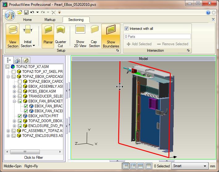
Forgot to put in that it would be nice if the cross-section interface was easier to use and much quicker.
Sep 23, 2010
06:16 AM
- Mark as New
- Bookmark
- Subscribe
- Mute
- Subscribe to RSS Feed
- Permalink
- Notify Moderator
Sep 23, 2010
06:16 AM
Hi,
dynamic cross-sections would be very helpful for sketching. If you're creating a sketch inside of a model it would be very helpful to create a cross-section on the sketching plane (with one click!). Maybe as an option: always_create_x-sec_on_sketching_plane yes*/no.
Oct 05, 2010
07:37 AM
- Mark as New
- Bookmark
- Subscribe
- Mute
- Subscribe to RSS Feed
- Permalink
- Notify Moderator
Oct 05, 2010
07:37 AM
Making a section on any of the flat surfaces of the assembly and components would be a great help.
At the moment if I want to check the engagement of a screw I need to show the screw plane add a assembly plane and create a section. ( you can also create the plane during the section but the plane as to be created).
Nicolas
Sep 08, 2010
05:23 PM
- Mark as New
- Bookmark
- Subscribe
- Mute
- Subscribe to RSS Feed
- Permalink
- Notify Moderator
Sep 08, 2010
05:23 PM
Folks,
Most of what we have been kicking around so far has to do with the User Interface, very important for clarity, efficiency, etc. Interestingly, this probably says--without saying--that the underlying substantive modeling capabilities are not where there is a deficiency. However, there is also room for improvement in geometry creation. The biggest thing I've wished for since I started (on 12.0) is a Swept Revolve. In other words: Give me what an endmill does!!! (More generally, what a rotating cutter does; and while you're at it, it might as well be capable of adding material in the same manner.)
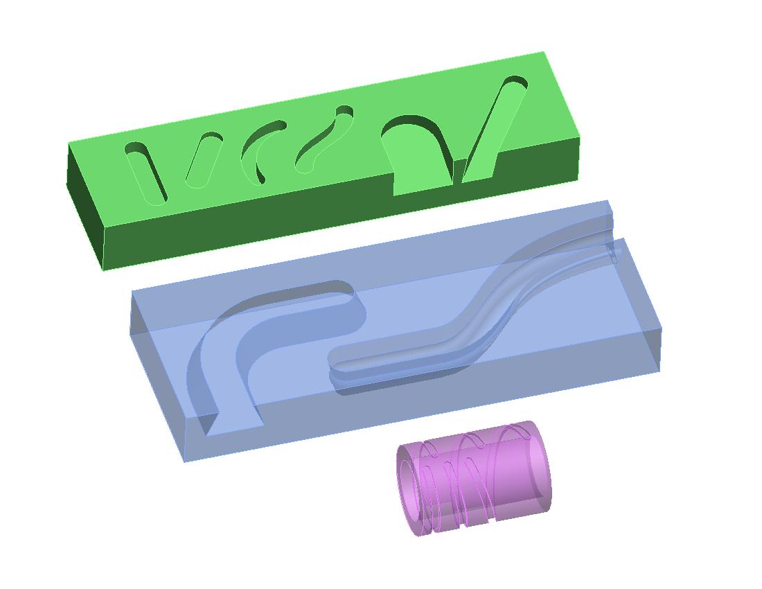
All of this geometry can be constructed using various Pro/E feature types and techniques, but how much easier some of them would be if you could just lay down a trajectory (and a half section only if necessary) and be done with it! Examples above include simple slots on the flat, inclined cuts, & cam slots on a cylinder produced with a standard end mill as well as a dovetail slot and a slot created with a form cutter. All of this geometric reality is already present in Pro/Manufacturing, NC-Check, and Vericut; it just needs to be enabled for modeling.
Those cam grooves on the cylinder (from a "real" project) are part of a pattern; having to add the end geometry in that case, then Reference Pattern, was particularly time-consuming, and sometimes on the edge of successful regeneration, depending on dimensions, etc.
David
Sep 08, 2010
05:44 PM
- Mark as New
- Bookmark
- Subscribe
- Mute
- Subscribe to RSS Feed
- Permalink
- Notify Moderator
Sep 08, 2010
05:44 PM
That is an excelent idea. It is always hard to get the end of a sweep to look like the end mill would create it. A swept revolve would be very helpful.
I was hoping for Geometry creation ideas like this, but I guess the ideas I put up so far were interface related. Thanks for pointing that out.
Sep 09, 2010
03:20 AM
- Mark as New
- Bookmark
- Subscribe
- Mute
- Subscribe to RSS Feed
- Permalink
- Notify Moderator
Sep 09, 2010
03:20 AM
+1.
Maybe more generally, it would be good to have the ability to sweep any volume (3D quilt) along a trajectory.
Could be used to produce hobbed, involute gears as well...
I tend to agree about UI improvements versus actual modelling capabilities, overall. Pro/E is pretty powerful and capable - just let us get at that capability quickly and simply!
Sep 09, 2010
09:24 AM
- Mark as New
- Bookmark
- Subscribe
- Mute
- Subscribe to RSS Feed
- Permalink
- Notify Moderator
Sep 09, 2010
09:24 AM
Interesting comment David. I've wished for the same thing for a while too. I did a barrel cam a few years ago for a mechanism, somewhat similar to what you modeled, and realized that the way it's modeled in Pro/E would not be the the way an end mill would actually cut the material. The endmill would actually remove a little MORE material, how much more would be dependent on the helix angle. It turned out to be a fairly big difference in some cases. Also, things like ball end milling cuts are more tricky to actually model too.
Sep 09, 2010
01:17 PM
- Mark as New
- Bookmark
- Subscribe
- Mute
- Subscribe to RSS Feed
- Permalink
- Notify Moderator
Sep 09, 2010
01:17 PM
Yeah, I meant to include a ball-milling example, too; very basic and important.
Sep 10, 2010
12:27 AM
- Mark as New
- Bookmark
- Subscribe
- Mute
- Subscribe to RSS Feed
- Permalink
- Notify Moderator
Sep 10, 2010
12:27 AM
Hi David,
Agree that this would be good geometry creation functionality. Several times over the years I have needed a swept 3D shape rather than a 2D section. Usually ends up with some fairly tricky construction. I thought the End Mill example was a particularly tricky one and have fortunately only had to do that once in 15 years. I would have thought that the technology that PTC already has in the two toolmaking modules would make this an easy task.
Regards, Brent
Oct 04, 2010
09:06 AM
- Mark as New
- Bookmark
- Subscribe
- Mute
- Subscribe to RSS Feed
- Permalink
- Notify Moderator
Oct 04, 2010
09:06 AM
A little follow-up, Re: Swept Blend request:
Just to be fair (to the capable geometry gurus at PTC) the request is not as easy to fulfill as it may seem. In general, the standard geometric techniques for sweeps and blends are much easier to execute because the sections do not extend out-of-plane. Just look at the simple example below. This shows 3 ways one might try to create a barrel cam slot (1" diameter barrel, 3/8" diameter cutter, 1/4" deep, pitch 2). Left to right: (1) Thru Axis rectangular section with cylinder dropped into the end, (2) Normal to Trajectory rectangular section with cylinder dropped into the end, and (3) Closely spaced pattern of cylinder drops to illustrate what actually happens. Take particular note of the thru-axis section boundaries. It may seem obvious that Thru Axis would be immediately rejected. However, because of the complexity of the situation, Thru Axis actually generates some of the real geometry that Normal to Trajectory does not, namely the flat bottom of the slot. Normal to Trajectory doesn't give us everything either because the cylindrical shape of the end mill "breaks out of" the twisted ribbon envelope of the simple sweep, giving a flared shape to the actual section. (The flare is made obvious in a normal-to-trajectory section.) Much more can be said about the details, but a picture will do here.
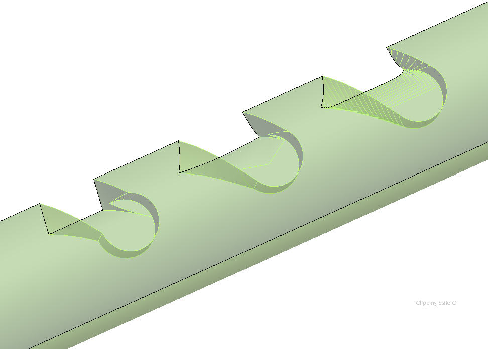
Bottom line: not easy, but all the more reason for nice to have.
Sep 08, 2010
05:50 PM
- Mark as New
- Bookmark
- Subscribe
- Mute
- Subscribe to RSS Feed
- Permalink
- Notify Moderator
Sep 08, 2010
05:50 PM
A lot of times when you are working on something you realize that it would be better to have two parts instead of one. It would be nice if you could put in a seperation line and have to part cut into to part files. It would be cool if Pro/E could be smart enough to then move the cut to the top of the model tree as the first feature. Then, remove all the references to the other part and make the cut sketch kind of like a skeleton model.
Not sure how to make a picture of this but I will work on something. Lots of times this situation comes up in sheetmetal parts too. So, it would be nice to have the capability in both solid modeling and sheetmetal.
Sep 09, 2010
01:56 PM
- Mark as New
- Bookmark
- Subscribe
- Mute
- Subscribe to RSS Feed
- Permalink
- Notify Moderator
Sep 09, 2010
01:56 PM
My wish for the project lightning is under.
(1) PATTERN IN THE SKETCH MODE.
(2) DRAFT IN SKETCH MODE.
(3) IMPORTING "IGES" & "STEP" FORMAT FILE AS FEATURE AT PART LEVEL AS WELL IN ADDITION TO ASSEMBLY. AND THE IMPORTED
FILE CAN BE ALLOWED TO BE CONSTRAINED ANY WHERE AT PART LEVEL OR ASSEMBLY LEVEL.
(4) EXTRUDE WITH DRAFT FOR DIFFERENT HEIGHTS ON BOTH SIDE OF PLANE.
Thanks.
Gautam Vora.
I am adding some more features in detailing the parts as wish list ( I think the wish list is like CHRISTMAS WISH LIST, AND SANTA NEVER FULL
FILLS OUR WISH LIST )
(1) FULL(ALIGNED) CROSS SECTION CAN BE INDEPENDENT AND OTHER PROJECTION VIEW CAN BE CREATED FROM THAT FULL (ALIGNED)
CROSS SECTION. THE DIMENSIONS SHOULD ALIGN ACCORDINGLY.
(2) FULL (UNFOLD) CROSS SECTION TOO.
Sep 10, 2010
12:50 AM
- Mark as New
- Bookmark
- Subscribe
- Mute
- Subscribe to RSS Feed
- Permalink
- Notify Moderator
Sep 10, 2010
12:50 AM
Hi Gautam,
I look on your points with some trepidation.
- Pattern in Sketch Mode. Yes this could be nice on occasion though I wonder how complex a sketch might end up to manage.
- Draft in Sketch Mode. I am not sure I know what you mean here. I sometimes put draft in a sketch and the usual issue is at smaller draft angles the sketch can get a bit unstable. I usually sketch at a large angle first, do my constraints, then set the draft angle. Typically this would be for swept surfaces where the draft function cannot do the job or where the draft is so fundamental to the part that it needs to be early in the model (not often).
- IGES import as an addition to part geometry and "assembled" as you would in assembly sounds like a fine idea. Right now I would make an assembly with my base part and import a separate IGES (or other) part, make copy surfaces and used publish geom and copy geom to bring those surfaces into my base part via the assembly. Your proposal would reduce this overhead. I know you can bring the IGES into a template part but there does not seem to be any control over position (default CYS).
- Extrude with Draft. My worry with this is it encouages draft earlier in the model and this can cause problems later on. As always there would be times when it is useful.
Regards, Brent
Sep 09, 2010
06:13 PM
- Mark as New
- Bookmark
- Subscribe
- Mute
- Subscribe to RSS Feed
- Permalink
- Notify Moderator
Sep 09, 2010
06:13 PM
ONE user interface to Rule Them All
This is fundamental to every user but hasnt been completed with WF5, so why introduce anything new - Lightning will just create more mess.
Frankly the vision required to fix this seems to be missing - Appearance Manager is a case in point.
PTC need to employ the best interface designers in the industry and get it sorted. Their UI managers need to know how the underlying product works and have actually used it. The rework of Appearance Manager shows that this is not the case.
Sep 09, 2010
06:20 PM
- Mark as New
- Bookmark
- Subscribe
- Mute
- Subscribe to RSS Feed
- Permalink
- Notify Moderator
Sep 09, 2010
06:20 PM
....But they were, all of them, deceived, for another Interface was made. In the land of PTC, in the fires of Mount doom, the Dark Lord Sauron forged in secret a Master Interface, to control all others. And into this Interface he poured his cruelty, his malice, and his will to dominate all users. 
Sep 09, 2010
06:51 PM
- Mark as New
- Bookmark
- Subscribe
- Mute
- Subscribe to RSS Feed
- Permalink
- Notify Moderator
Sep 09, 2010
06:51 PM
I suspect it has more to do with Dilbert than LOTR.
Good product requires management to have used it - in a Startup they have; in a SME they used to; in a Corporate they never have.
