
Turn on suggestions
Auto-suggest helps you quickly narrow down your search results by suggesting possible matches as you type.
Showing results for
Turn on suggestions
Auto-suggest helps you quickly narrow down your search results by suggesting possible matches as you type.
Showing results for
- Community
- Creo+ and Creo Parametric
- 3D Part & Assembly Design
- Re: Surface modelling to create curved glass
Options
- Subscribe to RSS Feed
- Mark Topic as New
- Mark Topic as Read
- Float this Topic for Current User
- Bookmark
- Subscribe
- Mute
- Printer Friendly Page
Surface modelling to create curved glass
Apr 29, 2015
05:41 AM
- Mark as New
- Bookmark
- Subscribe
- Mute
- Subscribe to RSS Feed
- Permalink
- Notify Moderator
Apr 29, 2015
05:41 AM
Surface modelling to create curved glass
Morning all,
I have a "surfacing" question that I hope someone can help with.
I'm attempting to reverse engineer a piece of glass to fit into an existing frame. The glass shape is quite complex in that its curved and twisted at the same time.
Step as follows below:
-Scanned the frame (on customers site) - this gives me a .stl file which is basically made up of load of facets.
-Import this into Creo.
-Then using a mixture of sketches, datum curves and boundary blends I have created a surface that replicates the new glass
-This surface can then be extended around the edges (to allow for some glass insertion into the frame, say 15 to 20mm all round)
-Then use 'thicken' to give the glass an 8mm thickness.
-Then 'flatten' to give a flat profile that is cut from sheet glass
-Lastly I would make a forming tool from the glass surface.
So, my problem is when I create the top and bottom sketches for the boundary blend I have to do these by eye. This looks OK at the start but the finished edge of the glass ends up slightly wobbly due to me picking the spline points by eye and then tweaking them to best suit the scanned frame data.
Can anyone give me any pointers on improving this? Or maybe a new / different approach to the whole job?
I have attached a Creo .prt file showing where I'm at with the scanned frame and the
Any help gratefully received.
Thanks, James
This thread is inactive and closed by the PTC Community Management Team. If you would like to provide a reply and re-open this thread, please notify the moderator and reference the thread. You may also use "Start a topic" button to ask a new question. Please be sure to include what version of the PTC product you are using so another community member knowledgeable about your version may be able to assist.
Solved! Go to Solution.
Labels:
- Labels:
-
Data Exchange
1 ACCEPTED SOLUTION
Accepted Solutions
May 01, 2015
10:19 AM
- Mark as New
- Bookmark
- Subscribe
- Mute
- Subscribe to RSS Feed
- Permalink
- Notify Moderator
May 01, 2015
10:19 AM
Send me a email contact and I will send you a rough cut vid directly. It will be specific to your part. I do not want to post potentially proprietary info for the world to see and get you in trouble with your boss. 
Me: -
11 REPLIES 11
May 01, 2015
06:40 AM
- Mark as New
- Bookmark
- Subscribe
- Mute
- Subscribe to RSS Feed
- Permalink
- Notify Moderator
May 01, 2015
06:40 AM
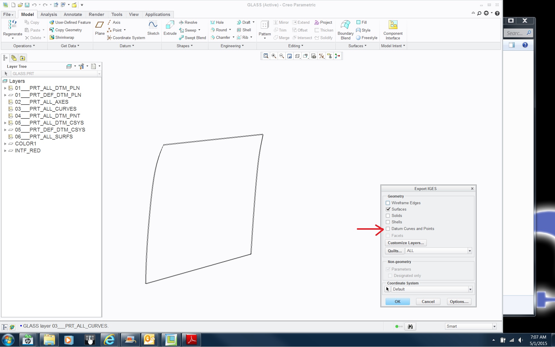
Save this as an IGES with curves. I only have Creo2.
I have done much surfacing (BIW, glass, etc...) on Pro (A.K.A. Creo)
May 01, 2015
07:02 AM
- Mark as New
- Bookmark
- Subscribe
- Mute
- Subscribe to RSS Feed
- Permalink
- Notify Moderator
May 01, 2015
07:02 AM
Thanks for the reply.
.iges file should now be attached.
James
May 01, 2015
07:19 AM
- Mark as New
- Bookmark
- Subscribe
- Mute
- Subscribe to RSS Feed
- Permalink
- Notify Moderator
May 01, 2015
07:19 AM
Need curves too.
May 01, 2015
07:52 AM
- Mark as New
- Bookmark
- Subscribe
- Mute
- Subscribe to RSS Feed
- Permalink
- Notify Moderator
May 01, 2015
08:08 AM
- Mark as New
- Bookmark
- Subscribe
- Mute
- Subscribe to RSS Feed
- Permalink
- Notify Moderator
May 01, 2015
08:08 AM
I've looked at the file, but don't have time to mess with it. The problem here is that this would likely be created as a larger surface and trimmed away. You don't have that luxury as you must meet the frame curves.
I've found that many spline points actually make creating a smooth surface harder. I'd try to create the end curves as simply as possible, perhaps two sketches intersected and try to use 2 point splines in each sketch. Add points only if you have to. The top & bottom sketches seem pretty simple, maybe just straight lines? Once you have simple curves, you should have better results.
Good luck, it's a deceptively simple looking part but I suspect will take some trial and error to get good results.
May 01, 2015
08:51 AM
- Mark as New
- Bookmark
- Subscribe
- Mute
- Subscribe to RSS Feed
- Permalink
- Notify Moderator
May 01, 2015
08:51 AM
James,
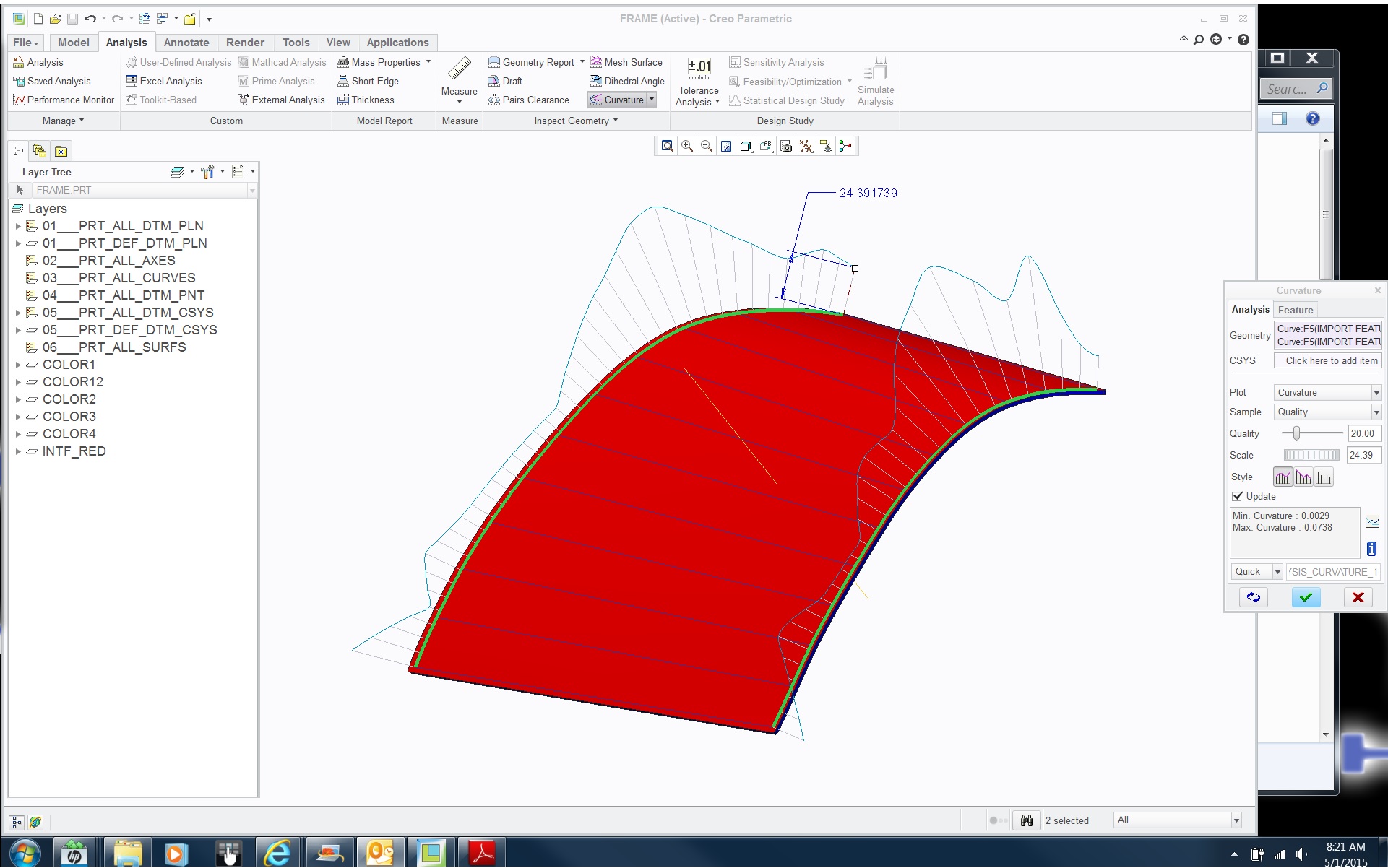
Since I cannot see the native 3.0 file I can't see exactly what is going on. But from what Doug Schaefer has said coupled from what I gather from the IGES, your boundary curves "order" is too high and you have said you are "eyeing it". You will need to use sweetened curves regardless of the final technique for the surface. Using sweetened curves is how you get the "wobble" out of your final glass. Surface development 101....do not use scans explicitly because...as you know...garbage in, garbage out. You have to approximate the scan curves with sweet (parsed) native curves.
Also, you should use the polygon option to pull the curve around instead of individual nodes. It will help get rid of the "chatter" in the curvature shown in the images. Also, I have found that if you are using "old school" Creo, (I.E. boundary surfaces instead of ISDX (actually both of those are "old school", but that is another discussion)) then the two curves driving the intersected resultant curve need to be created with care. Use the most parsed (lowest order) curves you can. Keep watching your curvature maps as you create your intersected curves too. Once you have the sweetened boundary curves all the rest are easy offsets.
If you need a video of the techniques I have explained, I can create one over lunch.
May 01, 2015
09:15 AM
- Mark as New
- Bookmark
- Subscribe
- Mute
- Subscribe to RSS Feed
- Permalink
- Notify Moderator
May 01, 2015
09:15 AM
Hi,
Wow that's a fantastic answer, I had thought that the wonky curves might be troublesome...
The whole 'surfacing' is very new to me and I've just been trying to learn as I go. If you could do a video to support what you've said it would be a massive help!!!
use sweetened curves..... how or what does this mean??
polygon option to pull the curve around.....this is also a new one on me???
boundary surfaces instead of ISDXboundary surfaces instead of ISDX...Ditto on this also....sorry???
I'm suddenly realising I don't know as much about Creo as I thought I did. Really appreciate your guidance on this - thanks. James
May 01, 2015
09:59 AM
- Mark as New
- Bookmark
- Subscribe
- Mute
- Subscribe to RSS Feed
- Permalink
- Notify Moderator
May 01, 2015
09:59 AM
James,
Wonky curves has always been a fact of surface development from CAD inception, not just Creo. The issue is Creo does not have all the cool tools to deal with it explicitly like a true Class A surface software does. We can get close but not 100%. So, we have to use all the tips, tricks and work-arounds to get to an acceptable solution.
Sorry, "sweetened" curves is my old school body design description for "developed" curve/surface creation. I use it to describe stuff that are Class A in nature. In this case, it would be a Creo curves that are lowest order curve to get the job done.
I call it polygon control but Creo calls it "modify spline using control points". It's the third icon from the left (Creo2) when modifying a spline.
Again sorry, ISDX is the old school description for the "Style" feature. That's what it was called long, long ago in a galaxy far, far away. Style is the closest thing Creo comes to a Class A surface tool. I use it for most of the surfaces I do now. It would be the better choice for your part but it comes with a little learning curve. You can certainly still get the result you are after using the boundary surface technique.
I will put together a video and post it to my YouTube Channel later. NeuTech Design - YouTube
Dean
May 01, 2015
10:06 AM
- Mark as New
- Bookmark
- Subscribe
- Mute
- Subscribe to RSS Feed
- Permalink
- Notify Moderator
May 01, 2015
10:06 AM
Brilliant, thanks Dean.
I can enjoy a bank holiday weekend now without stressing so much about surfacing.... 
James
May 01, 2015
10:19 AM
- Mark as New
- Bookmark
- Subscribe
- Mute
- Subscribe to RSS Feed
- Permalink
- Notify Moderator
May 01, 2015
10:19 AM
Send me a email contact and I will send you a rough cut vid directly. It will be specific to your part. I do not want to post potentially proprietary info for the world to see and get you in trouble with your boss.
Me: -
May 01, 2015
10:29 AM
- Mark as New
- Bookmark
- Subscribe
- Mute
- Subscribe to RSS Feed
- Permalink
- Notify Moderator
May 01, 2015
10:29 AM
i like to think I know high end surfacing, but then I here someone like you explain things and I realize I've got much to learn.
