
Turn on suggestions
Auto-suggest helps you quickly narrow down your search results by suggesting possible matches as you type.
Showing results for
Turn on suggestions
Auto-suggest helps you quickly narrow down your search results by suggesting possible matches as you type.
Showing results for
Community Tip - Did you get an answer that solved your problem? Please mark it as an Accepted Solution so others with the same problem can find the answer easily. X
- Community
- Creo+ and Creo Parametric
- 3D Part & Assembly Design
- importing iges/step assys into creo 2.0
Options
- Subscribe to RSS Feed
- Mark Topic as New
- Mark Topic as Read
- Float this Topic for Current User
- Bookmark
- Subscribe
- Mute
- Printer Friendly Page
importing iges/step assys into creo 2.0
Apr 02, 2015
06:36 PM
- Mark as New
- Bookmark
- Subscribe
- Mute
- Subscribe to RSS Feed
- Permalink
- Notify Moderator
Apr 02, 2015
06:36 PM
importing iges/step assys into creo 2.0
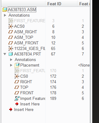
Why is it even when I select ASSEMBLY as my import option I'm still getting a part that won't go solid?? (ignore the part numbers this is an iges file)
from Amphenol 112234 112234 - BNC Straight Crimp Jack for RG-174, RG-316, LMR-100, 50 Ohm, Bulkhead - Amphenol Connex
This thread is inactive and closed by the PTC Community Management Team. If you would like to provide a reply and re-open this thread, please notify the moderator and reference the thread. You may also use "Start a topic" button to ask a new question. Please be sure to include what version of the PTC product you are using so another community member knowledgeable about your version may be able to assist.
Labels:
- Labels:
-
Data Exchange
3 REPLIES 3
Apr 03, 2015
06:57 AM
- Mark as New
- Bookmark
- Subscribe
- Mute
- Subscribe to RSS Feed
- Permalink
- Notify Moderator
Apr 03, 2015
06:57 AM
Unfortunately, I've had some experience with this. Lots of component suppliers are nice and let us download models of their stuff so we can make sure of fit and all that. Many of the models are generated by an automated system. What I've found is that most of the time, if the model is not solidified (it's just a bunch of surfaces), it's because one or more of the surfaces failed, making the set of surfaces non-manifold.
Now, how to deal with it. Things I've done in the past:
(1) Redefine the import feature. You might, if the offending surface is evident, be able to fix it. This has only worked a very few times.
(2) If the model is somewhat simple in nature, I'll use the imported stuff as a guideline and remodel the part myself. This has the added benefit of making a file that is much smaller in size than the imported one.
(3) Accept the surfaced model and move on. I hate this option, but on things like motors with cast in cooling fins and odd shapes, it's just not justifiable to spend the amount of time I'd need to use options (1) or (2).
Apr 03, 2015
07:15 AM
- Mark as New
- Bookmark
- Subscribe
- Mute
- Subscribe to RSS Feed
- Permalink
- Notify Moderator
Apr 03, 2015
07:15 AM
Another 'fix' that sometimes works is to change the accuracy of the imported part (usually increasing the value). If you're lucky, this will get you a solid model - particularly useful on those complex castings.
Apr 12, 2015
05:55 AM
- Mark as New
- Bookmark
- Subscribe
- Mute
- Subscribe to RSS Feed
- Permalink
- Notify Moderator
Apr 12, 2015
05:55 AM
Hi Terry,
I'm sorry, that you have so much trouble with a standard part like this.
I have had a look in the IGES file. It's converted from Pro/E in flat (one level) mode. So, you can only get a single model.
That's normal for standard parts like BNC ... The supplier data library have a lot of them.
If you open a iges file Creo recognize the model mode and makes atomatically a tick on the right option (part or assembly).
In case of IGES structure, you get more than one IGES file normally. In STEP you have different options.
To import interface data it's important which kind of default accuracy you have.
In our company we take Absolute 0.01. If i read the iges file, the surface is quite ok and i get a solid.
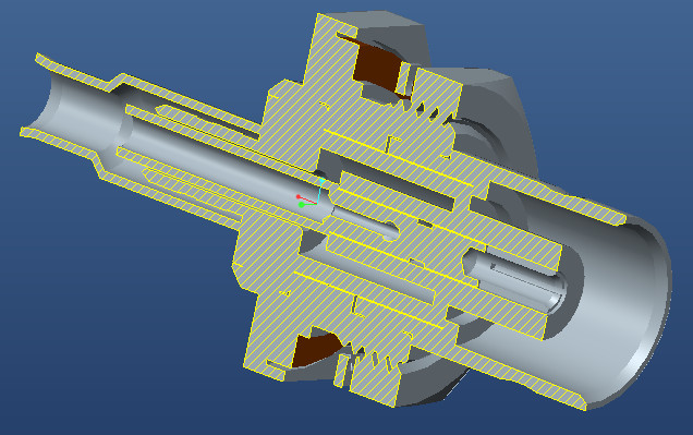
I have tried it with several other model options and i get also only surface (with gaps), that couldn't automatically closed.
In this case i need my Creo doctor.
If you want, you can upload the corrupt Creo file and i will have a look.
Best whishes
Wolfgang
