
Turn on suggestions
Auto-suggest helps you quickly narrow down your search results by suggesting possible matches as you type.
Showing results for
Turn on suggestions
Auto-suggest helps you quickly narrow down your search results by suggesting possible matches as you type.
Showing results for
Community Tip - You can change your system assigned username to something more personal in your community settings. X
- Community
- Creo+ and Creo Parametric
- 3D Part & Assembly Design
- 3D Dimension plane
Options
- Subscribe to RSS Feed
- Mark Topic as New
- Mark Topic as Read
- Float this Topic for Current User
- Bookmark
- Subscribe
- Mute
- Printer Friendly Page
3D Dimension plane
Mar 23, 2012
11:22 AM
- Mark as New
- Bookmark
- Subscribe
- Mute
- Subscribe to RSS Feed
- Permalink
- Notify Moderator
Mar 23, 2012
11:22 AM
3D Dimension plane
I have a drawing with a 3D view on it. I'm able to get all the dimensions that I need shown but they seem to be located on some plane outside the extents of my model so there's no way to tell where the dimension lines are pointing. How can I change the plane the dimensions are shown on?
Thanks
This thread is inactive and closed by the PTC Community Management Team. If you would like to provide a reply and re-open this thread, please notify the moderator and reference the thread. You may also use "Start a topic" button to ask a new question. Please be sure to include what version of the PTC product you are using so another community member knowledgeable about your version may be able to assist.
Labels:
- Labels:
-
2D Drawing
15 REPLIES 15
Mar 23, 2012
11:23 AM
- Mark as New
- Bookmark
- Subscribe
- Mute
- Subscribe to RSS Feed
- Permalink
- Notify Moderator
Mar 23, 2012
11:23 AM
This is Creo 1.0 by the way.
Mar 23, 2012
11:35 AM
- Mark as New
- Bookmark
- Subscribe
- Mute
- Subscribe to RSS Feed
- Permalink
- Notify Moderator
Mar 23, 2012
11:35 AM
Are these (1) 3D dimensions created in model space or (2) are you trying to place dimensions on the isometric drawing view?
If (2), you'll have no luck. 3D dimensions are made in model space and then can be shown on the drawing using "Show Model Annotations" if you have the config option auto_show_3d_detail_items set to yes.
Do you need help creating 3D dimensions (actually they're "annotations") in model space?
Regards,
Kevin
Mar 23, 2012
11:38 AM
- Mark as New
- Bookmark
- Subscribe
- Mute
- Subscribe to RSS Feed
- Permalink
- Notify Moderator
Mar 23, 2012
11:38 AM
I used the Show Annotations dialog box on my Drawing to show the dims I needed.
Mar 23, 2012
11:46 AM
- Mark as New
- Bookmark
- Subscribe
- Mute
- Subscribe to RSS Feed
- Permalink
- Notify Moderator
Mar 23, 2012
11:46 AM
Are the orientations of the dims different in model space than in drawing mode?
Mar 23, 2012
11:54 AM
- Mark as New
- Bookmark
- Subscribe
- Mute
- Subscribe to RSS Feed
- Permalink
- Notify Moderator
Mar 23, 2012
11:54 AM
actually, when I used the same Show Dimension button in Modelspace, they showed up in modelspace but not in the drawing... even if I deleted the view and added it again. I turned on allow_3d_dimensions, clicked Show Dimension on the drawing, and selected the check-boxes for the dimensions I wanted to show. after that, they showed up in the drawing, just not quite pointing to the right place.
here's the whole story (and possibly why they look to be pointing to the wrong spot). I made a model that's driven by Pro/Program and some relations. It brings in dimension and text values from a text file and applies them to DATUM PLANES. the model is then related to those datum planes to automate my modeling process somewhat. when I add these dimensions to the 3D view, it's actually dimensioning the datum planes rather than the part itself. I'm not sure how to see datum planes displayed in a 3D view but I'm thinking maybe these dimension lines are pointing to the edges of where the planes would be displayed if they were visible. could that be what it's doing? and if so, how do I change that?
Mar 23, 2012
01:01 PM
- Mark as New
- Bookmark
- Subscribe
- Mute
- Subscribe to RSS Feed
- Permalink
- Notify Moderator
Mar 23, 2012
01:01 PM
Some things are confusing. For instance, I don't know what you mean by "Show Dimension button in Modelspace".
Can you provide images of the model dimensioned in 3D space and in the drawing? Use the same orientation for the model in each case.
In the meantime I'll make a video that shows how to place annotations on the model and then show them on the drawing. That may help more than anything else.
Mar 23, 2012
01:11 PM
- Mark as New
- Bookmark
- Subscribe
- Mute
- Subscribe to RSS Feed
- Permalink
- Notify Moderator
Mar 23, 2012
01:11 PM
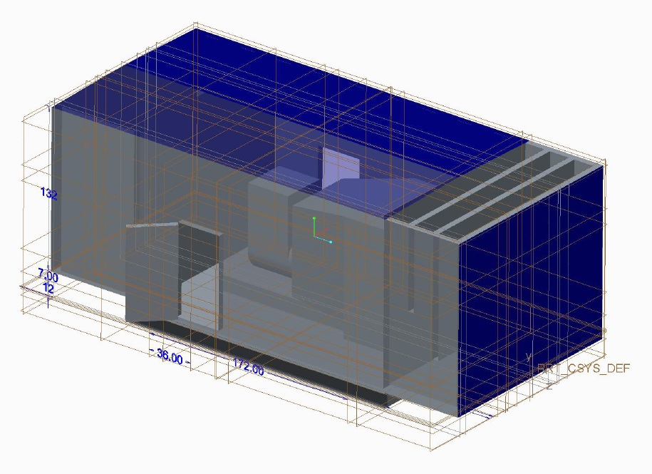
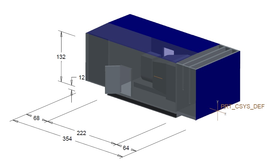
OK... the top picture is from modelspace and has the datum planes shown.
the bottom one is the drawing and has the dimensions as I want to show them.
if you look at the 132 dimension, for instance, it looks like it's pointing to the edges of where the top and bottom datum planes are pictured in the first one. might this be the case?
the dimension on the plane that the 354 dimension is on look to be on the correct plane but aren't extended nearly far enough toward the model... maybe also indicating that they're just pointing to the edges of the left/right datum planes.
not sure what the best way to handle the display of datum planes is either if that's what the issue is.
Mar 23, 2012
01:41 PM
- Mark as New
- Bookmark
- Subscribe
- Mute
- Subscribe to RSS Feed
- Permalink
- Notify Moderator
Mar 23, 2012
01:41 PM
Click the link below for suggestions that should help you. For some of your dimensions you will be able to drag the endpoints of the extension lines and for others you will have to change the reference plane that the dimensions lie on.
2 tips for manipulating annotation in Creo Elements/Pro 5.0
I don't know how this technique will vary since you are using Creo 1.0.
***Earlier I mentioned the config option that would allow 3D dims in a drawing and I was mistaken. Its not a config option, it is the drawing option allow_3D_dimensions.
Regards,
Kevin
Mar 23, 2012
01:49 PM
- Mark as New
- Bookmark
- Subscribe
- Mute
- Subscribe to RSS Feed
- Permalink
- Notify Moderator
Mar 23, 2012
01:49 PM
hey thanks for the video Kevin. it seems to be the same process in Creo. I think my issue was that I was attempting to dimension in the drawing rather than on the model... Is it easier to work with the dims if I dimension in model space instead?
I haven't tried this process yet as I am temporarily disconnected from my license server but is the auto_show_3D_detail_items option the one that will make my dimensions from model space show up in the drawing? because they previously were not shown.
Mar 23, 2012
01:55 PM
- Mark as New
- Bookmark
- Subscribe
- Mute
- Subscribe to RSS Feed
- Permalink
- Notify Moderator
Mar 23, 2012
01:55 PM
To sum it up, if you want dimensions to show properly on an isometric drawing view then you will have to
(1) Create the dims in model space and
(2) set the drawing option (not config option) allow_3D_dimensions to yes.
Regards,
Kevin
Mar 26, 2012
03:43 PM
- Mark as New
- Bookmark
- Subscribe
- Mute
- Subscribe to RSS Feed
- Permalink
- Notify Moderator
Mar 26, 2012
03:43 PM
I've found several ways to have the dimensions display on the iso view, none of which are showing correctly still. The dimensions are POINTING to the correct planes, but are not being DISPLAYED on the correct plane. Again, if you look at the second screen capture I uploaded earlier in this thread, you can see that the dimensions showing my height are not (and still not) displaying on the correct annotation plane.
I also tried setting my active annotation plane to be on the left side of my structure (the front left long side of this structure), adding dimensions via the "dimension" function in modelspace, then showing those dimensions labeled (in this case) "ad280" and "ad281" in my drawing. It still displays them on some plane that isn't the left side of the structure.... making it look as though those witness lines aren't pointing to anything in particular, when it should be pointing at the top and bottom of this structure. Extending those witness lines obviously won't extend them to the correct location either.
UGH
Mar 26, 2012
03:56 PM
- Mark as New
- Bookmark
- Subscribe
- Mute
- Subscribe to RSS Feed
- Permalink
- Notify Moderator
Mar 26, 2012
03:56 PM
Chris,
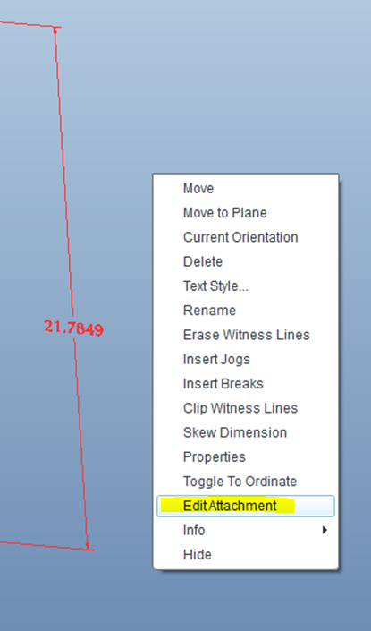
Do you have to use the planes as dim refs? Would it not give you the same result if you use the edges highlighted red below as the dim refs for 132? You can create new dims or redefine the existing dims (see 2nd image) and choose the edges. Also, the surface between the edges would have to be the current annotation plane when you place the dim.
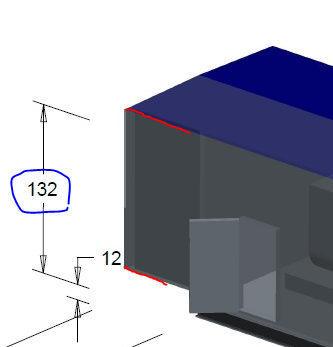
"Edit attachment" to select new refs for the dim. Don't forget, to select annotations you need to set the selection filter to "Annotation".
Mar 26, 2012
04:08 PM
- Mark as New
- Bookmark
- Subscribe
- Mute
- Subscribe to RSS Feed
- Permalink
- Notify Moderator
Mar 26, 2012
04:08 PM
THAT WORKS! I would have liked to have used the planes as the entities to attach to since those are actually what's driven by my relations and I'm 100% sure they won't go changing on me, but this will have to do... at least until I can convince my company to buy me the advanced assembly module so I can make this same concept model out of more than one part file.
Thanks a lot, Kevin.
Nov 12, 2016
01:53 AM
- Mark as New
- Bookmark
- Subscribe
- Mute
- Subscribe to RSS Feed
- Permalink
- Notify Moderator
Nov 12, 2016
01:53 AM
THANKS KEVIN.THAT HELPED ME
Mar 23, 2012
01:21 PM
- Mark as New
- Bookmark
- Subscribe
- Mute
- Subscribe to RSS Feed
- Permalink
- Notify Moderator
Mar 23, 2012
01:21 PM
I should also probably specify that this is a single part (not an assembly). I wanted to drive the model with Pro/Program but I don't have the Advanced Assembly add-on so I cannot access the Program command in assembly mode.
