
Turn on suggestions
Auto-suggest helps you quickly narrow down your search results by suggesting possible matches as you type.
Showing results for
Turn on suggestions
Auto-suggest helps you quickly narrow down your search results by suggesting possible matches as you type.
Showing results for
Community Tip - You can Bookmark boards, posts or articles that you'd like to access again easily! X
- Community
- Creo+ and Creo Parametric
- 3D Part & Assembly Design
- Re: AutoGEM ERROR
Options
- Subscribe to RSS Feed
- Mark Topic as New
- Mark Topic as Read
- Float this Topic for Current User
- Bookmark
- Subscribe
- Mute
- Printer Friendly Page
AutoGEM ERROR
Jul 22, 2017
06:07 AM
- Mark as New
- Bookmark
- Subscribe
- Mute
- Subscribe to RSS Feed
- Permalink
- Notify Moderator
Jul 22, 2017
06:07 AM
AutoGEM ERROR
Hi.
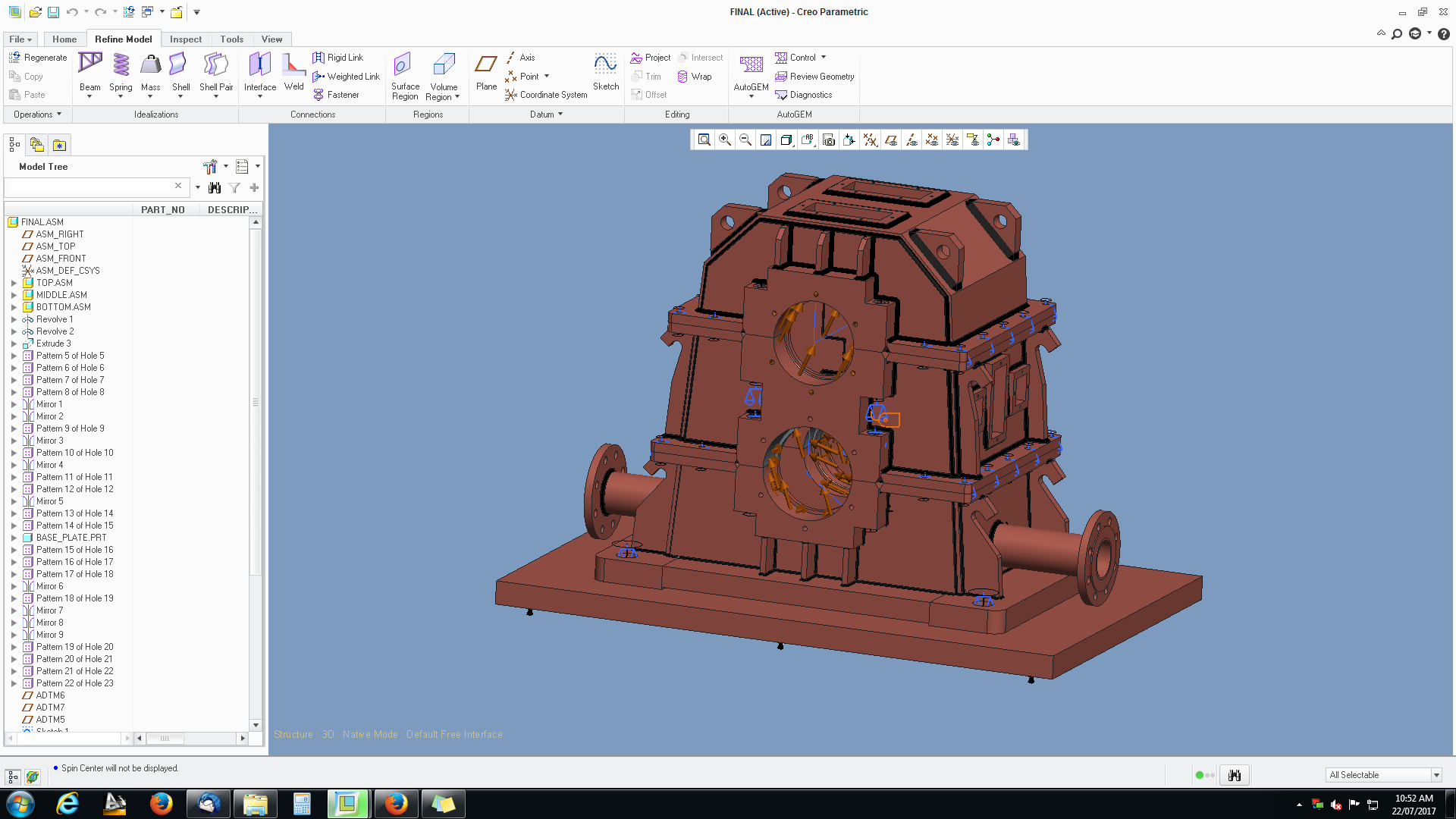
I have modeled a gearbox casing which consist of three different sub assemblies(Top, Middle and bottom which was modeled in TOP-DOWN approach) composed of fabricated steel plates using CREO-2.0 for structural analysis. I have provided fastener connection between these three sub assemblies. In each sub assemblies, I have used weldment feature for joining the different plates(It is also defined under simulate menu). During meshing(AutoGEM) I'm getting 4 errors in the diagnostics tab as following.
1. Creo Simulate removed some small curves from the model. The removal tolerance is set from the Geometry Tolerance dialog box (AutoGEM > Geometry Tolerance). Fewer curves are removed if you decrease the Minimum Curve Dimension value.
2. AutoGEM may not be able to complete because the volume boundaries either intersect or overlap near the highlighted surfaces
3. The ratio of the thickness to the radius of curvature is too large for the highlighted surface(s). The thickness multiplied by the maximum curvature must be less than 1.5.
4. AutoGEM approximated invalid elements.
As I'm new to analysis, I do not know how to solve it. Please help me to rectify the error and to solve.
Herewith I have attached the screenshot of the model.
Labels:
- Labels:
-
2D Drawing
4 REPLIES 4
Jul 24, 2017
11:52 PM
- Mark as New
- Bookmark
- Subscribe
- Mute
- Subscribe to RSS Feed
- Permalink
- Notify Moderator
Jul 24, 2017
11:52 PM
Ragu,
We do Creo Simulate analysis of similar welded structures.
What we do is always, there is no part to part contacts. only the welds will connect the parts together, so there is .02" gap between the plates. You can also use the Review Geometry option to see if there are proper contacts.
Jul 25, 2017
01:00 AM
- Mark as New
- Bookmark
- Subscribe
- Mute
- Subscribe to RSS Feed
- Permalink
- Notify Moderator
Jul 25, 2017
01:00 AM
Thanks for your response MRV.
In the model setup, I have chosen bonded as my default interface. Will I get proper result If I maintain 0.05" gap between the plates or should i want to change the default interface?
Jul 25, 2017
01:06 AM
- Mark as New
- Bookmark
- Subscribe
- Mute
- Subscribe to RSS Feed
- Permalink
- Notify Moderator
Jul 25, 2017
01:06 AM
We maintain the gap since this is the practical method to allow the weld material to flow inside the gap and we never had issues with this method. we never build a welded structure assembly with parts touching. So this may help, but again there may be other issues as well which I can't comment on without studying the models.
Jul 25, 2017
01:27 AM
- Mark as New
- Bookmark
- Subscribe
- Mute
- Subscribe to RSS Feed
- Permalink
- Notify Moderator
Jul 25, 2017
01:27 AM
Thanks MRV.
Let me give a try for your idea.
