
Turn on suggestions
Auto-suggest helps you quickly narrow down your search results by suggesting possible matches as you type.
Showing results for
Turn on suggestions
Auto-suggest helps you quickly narrow down your search results by suggesting possible matches as you type.
Showing results for
Community Tip - Have a PTC product question you need answered fast? Chances are someone has asked it before. Learn about the community search. X
- Community
- Creo+ and Creo Parametric
- 3D Part & Assembly Design
- Cross section in 3D environment
Options
- Subscribe to RSS Feed
- Mark Topic as New
- Mark Topic as Read
- Float this Topic for Current User
- Bookmark
- Subscribe
- Mute
- Printer Friendly Page
Cross section in 3D environment
Sep 20, 2014
01:36 PM
- Mark as New
- Bookmark
- Subscribe
- Mute
- Subscribe to RSS Feed
- Permalink
- Notify Moderator
Sep 20, 2014
01:36 PM
Cross section in 3D environment
Hi to all,
i created a cross section in 3D environment. Can i use it in drawing with same hatches and included/exclude components?
Thank you for help.
This thread is inactive and closed by the PTC Community Management Team. If you would like to provide a reply and re-open this thread, please notify the moderator and reference the thread. You may also use "Start a topic" button to ask a new question. Please be sure to include what version of the PTC product you are using so another community member knowledgeable about your version may be able to assist.
Labels:
- Labels:
-
2D Drawing
14 REPLIES 14
Sep 20, 2014
01:47 PM
- Mark as New
- Bookmark
- Subscribe
- Mute
- Subscribe to RSS Feed
- Permalink
- Notify Moderator
Sep 20, 2014
01:47 PM
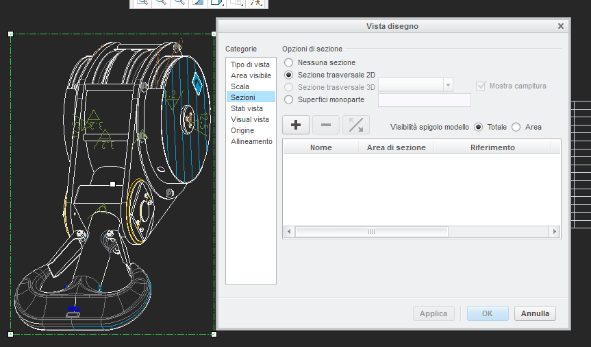
It seems i can't add 3D sections on 2D drawings...
Sep 20, 2014
07:21 PM
- Mark as New
- Bookmark
- Subscribe
- Mute
- Subscribe to RSS Feed
- Permalink
- Notify Moderator
Sep 20, 2014
07:21 PM
I think you don't have any 3D sections. You have a 2D (planar) section
Click the "+" button to add a section to the view.
Sep 21, 2014
05:56 AM
- Mark as New
- Bookmark
- Subscribe
- Mute
- Subscribe to RSS Feed
- Permalink
- Notify Moderator
Sep 21, 2014
05:56 AM
Mauro,
my suggestion is ... do a simple test to be sure that Creo works fine.
1.] create an assembly named TEST containing two simple models (eg. CYLINDER1, CYLINDER2)
2.] create a planar crossection A in TEST assembly in Assembly mode
3.] create a drawing named TEST and put the assembly named TEST in the drawing
4.] place a view with crosssection (it is visible as 2D crosssection in view properties window) into the drawing - orient it properly crosssection plane must be parallel with the display
If the test is successfull then you have to find the difference between it and your real drawing.
Martin Hanak
Martin Hanák
Sep 21, 2014
01:37 PM
- Mark as New
- Bookmark
- Subscribe
- Mute
- Subscribe to RSS Feed
- Permalink
- Notify Moderator
Sep 21, 2014
01:37 PM
Sorry Martin, i was too short in explanation of my trouble (i'm bad in english). I already did your test. My 2D cross section is not equal to 3D cross section. Included and excluded components in 3D aren't inclueded and excluded as in 2D and i have to define them in 2D drawing. Another question is: why option in red is grey? Is grey for any orientation of view. 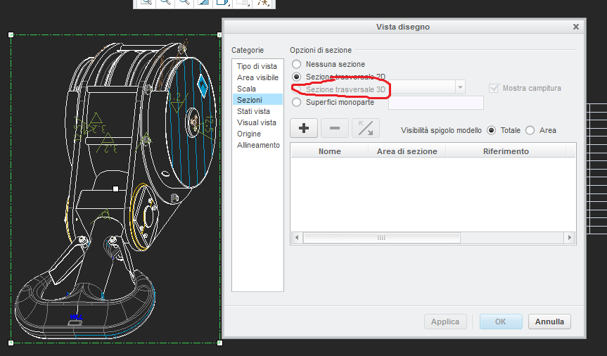
Sep 21, 2014
01:54 PM
- Mark as New
- Bookmark
- Subscribe
- Mute
- Subscribe to RSS Feed
- Permalink
- Notify Moderator
Sep 21, 2014
01:54 PM
The help files provded some understanding on when this option is available.
You need to use the "zone" definition in the xsection dialog in the model.
Once you create one of these, it will always be available in your drawing view.
There is no preview, and it is a very confusong dialog to understand what you will end up with.
A little practice and you'll have what you need.
http://help.ptc.com/creo_hc/creo30_pma_hc/usascii/index.html#page/pma/detail/section_create_3d.html
Sep 21, 2014
02:16 PM
- Mark as New
- Bookmark
- Subscribe
- Mute
- Subscribe to RSS Feed
- Permalink
- Notify Moderator
Sep 21, 2014
02:16 PM
Thank you so much Antonius, i understood zone sections but options like include/exclude component aren't available. I try to change offset cross section in 3D but nothing changes in 2D. Anyway fortunately i have at maximum 30 components on cross sections. Sometimes is difficult to select manually components to be excluded for cross sections in 2D. I know tricks to work easy in assembly drawings, but i hate assembly drawings.. 😉
Sep 21, 2014
02:26 PM
- Mark as New
- Bookmark
- Subscribe
- Mute
- Subscribe to RSS Feed
- Permalink
- Notify Moderator
Sep 21, 2014
02:26 PM
There are some serious issues and limitations with making nice 3D sections. I resort to a next level assembly with an assembly cut through the parts I want. There, I can also use colors to show the sectioned faces rather than a hatch that may or may not be accurately displayed. This method is so much more powerful that I don't even look back.
Sep 22, 2014
08:57 AM
- Mark as New
- Bookmark
- Subscribe
- Mute
- Subscribe to RSS Feed
- Permalink
- Notify Moderator
Sep 22, 2014
08:57 AM
When I create a planar 2D cross section in my assembly and exclude a component and then go to the drawing and add a view (default orientation in my case) with the 2D section specified, it uses the excluded component as I specified in the model.
I don't understand what the 3D cross section at all but I think I get the result you are looking for.
Sep 22, 2014
02:18 PM
- Mark as New
- Bookmark
- Subscribe
- Mute
- Subscribe to RSS Feed
- Permalink
- Notify Moderator
Sep 22, 2014
02:18 PM
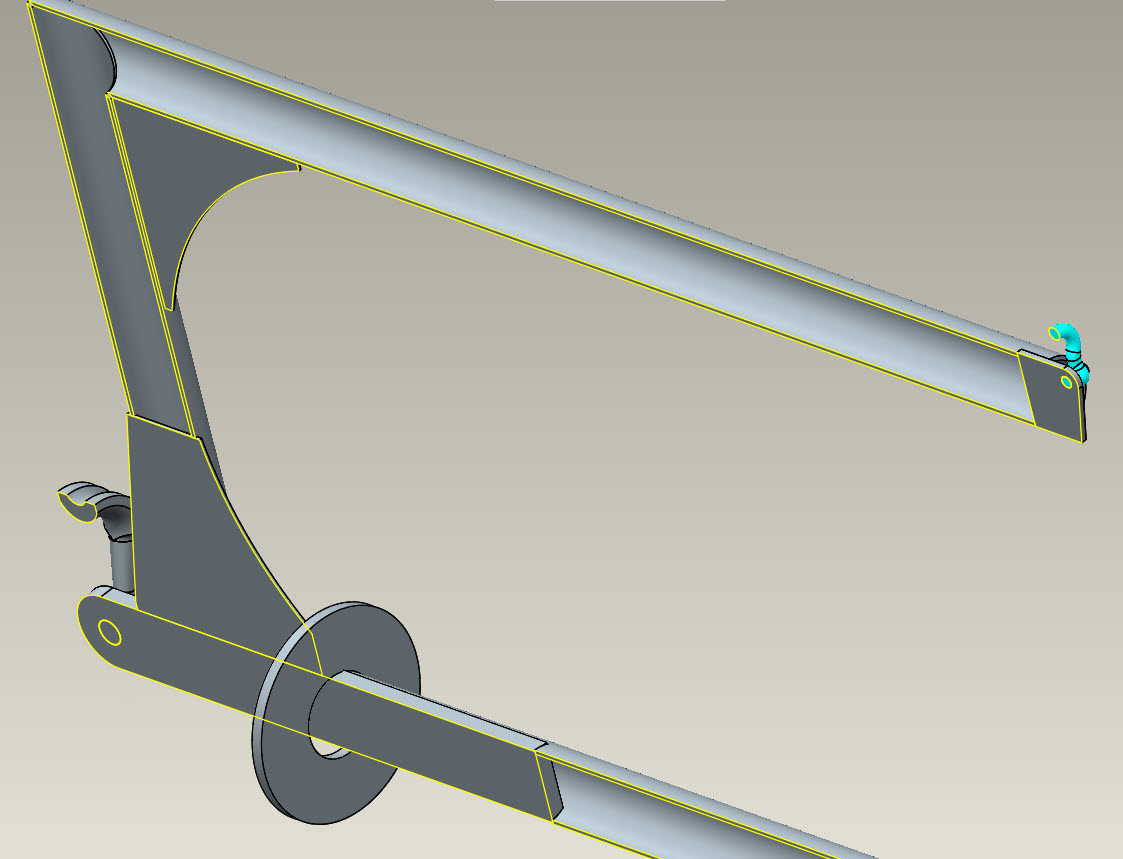
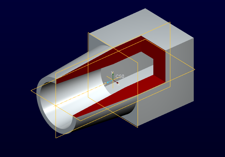
The most common requirement is to remove a single quadrant cube from a part or assembly.
The problem with offset sections is that is must go through the part in both directions.
The problem with 3D section (Zones) is that it removes the wrong half.
This should be easy to do but seems extraordinarily difficult to achieve using sections.
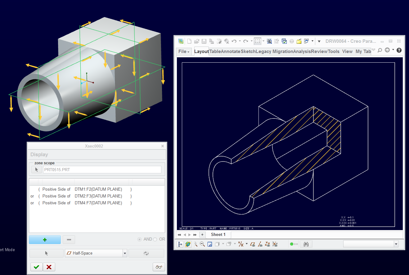
Now put that in a drawing with cross hatching 
(yes, this is a cut; Pro|WorkAround^tm 1,087,194)
Sep 22, 2014
03:20 PM
- Mark as New
- Bookmark
- Subscribe
- Mute
- Subscribe to RSS Feed
- Permalink
- Notify Moderator
Sep 22, 2014
03:20 PM
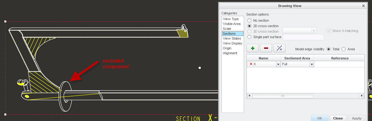
This is what I came up with using Zone... but in the drawing, I couldn't change the cross hatch pattern.
I'm afraid we might be defining 3D sections two different ways. Sections and view orientation are independent. Offset and planar sections can be displayed in any view orientation. Limitations are only presented when views are projected and the section is not compatible for some reason.
Sep 22, 2014
03:08 PM
- Mark as New
- Bookmark
- Subscribe
- Mute
- Subscribe to RSS Feed
- Permalink
- Notify Moderator
Sep 22, 2014
03:08 PM
You're right Stephen. For me section 2D corresponds to 3D section first time. Then, if i update 3D section, 2D section doesn't change. Also if i delete view and recreate section (Creo 2.0 M120).
Sep 22, 2014
03:11 PM
- Mark as New
- Bookmark
- Subscribe
- Mute
- Subscribe to RSS Feed
- Permalink
- Notify Moderator
Sep 22, 2014
03:11 PM
I agree, the cross section include/exclude don't seem to be parametric. Once it's on the drawing, it seem to be a snapshot in time.
Sep 22, 2014
03:24 PM
- Mark as New
- Bookmark
- Subscribe
- Mute
- Subscribe to RSS Feed
- Permalink
- Notify Moderator
Sep 22, 2014
03:24 PM
I use the exlude 2D sections a lot and it is dynamic.
Add a part, exclude it, and it updates on the drawing.
Remove excluded components, and they do update in the drawing.
You might have to regenerate the drawing to get this to update.
Sep 22, 2014
03:31 PM
- Mark as New
- Bookmark
- Subscribe
- Mute
- Subscribe to RSS Feed
- Permalink
- Notify Moderator
Sep 22, 2014
03:31 PM
Also don't forget that you can exclude components on drawings such as covers and such to expose details.
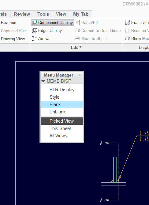
