
Turn on suggestions
Auto-suggest helps you quickly narrow down your search results by suggesting possible matches as you type.
Showing results for
Turn on suggestions
Auto-suggest helps you quickly narrow down your search results by suggesting possible matches as you type.
Showing results for
Community Tip - Learn all about PTC Community Badges. Engage with PTC and see how many you can earn! X
- Community
- Creo+ and Creo Parametric
- 3D Part & Assembly Design
- How do make a view similar to exploded but control...
Options
- Subscribe to RSS Feed
- Mark Topic as New
- Mark Topic as Read
- Float this Topic for Current User
- Bookmark
- Subscribe
- Mute
- Printer Friendly Page
How do make a view similar to exploded but controlled
May 13, 2016
05:02 PM
- Mark as New
- Bookmark
- Subscribe
- Mute
- Subscribe to RSS Feed
- Permalink
- Notify Moderator
May 13, 2016
05:02 PM
How do make a view similar to exploded but controlled
What is the easiest way to make views on prints where you can show stages of movement with certain parts of an assembly?
So in other words, I want to show on print a group of parts moved away from another group of parts and at a specific distance (and then put a dimension between them).
I've seen this work easily in other CAD software but I have not had luck figuring out a quick and easy way in Creo 2.
This thread is inactive and closed by the PTC Community Management Team. If you would like to provide a reply and re-open this thread, please notify the moderator and reference the thread. You may also use "Start a topic" button to ask a new question. Please be sure to include what version of the PTC product you are using so another community member knowledgeable about your version may be able to assist.
Labels:
- Labels:
-
2D Drawing
9 REPLIES 9
May 13, 2016
08:54 PM
- Mark as New
- Bookmark
- Subscribe
- Mute
- Subscribe to RSS Feed
- Permalink
- Notify Moderator
May 13, 2016
08:54 PM
For explode states, that can't happen. However, a useful simulation is to set the distance that items are dragged to a useful value, like 10 inches or 100mm or to the amount you want the offset to be - even 1.25 inches is OK.
Explode won't stop when dragged to that distance, but it will snap to that distance, and there is an on-screen display of how far an item has been dragged. For angle, Creo uses integer multiples from zero, so setting it to 7 degrees will snap to 7 degrees in one direction, but not in the other (whatever the largest multiple of 7 that is less than 360, for example)
I guess you could try to create a datum curve that represents where the parts will end up and show the dimensions for that, but it is tedious. Not sure if it will work as I've not shown dimensions in explode states.
The alternative is to build the assembly so the offsets can be used to make the explosion as a family table item, or to place the target assy into a dummy assembly and use flexible dimensions to move the parts - leaving the original assembly otherwise unchanged.
The last shot would be to export as a STEP file and re-import and reassemble as desired.
May 15, 2016
03:19 PM
- Mark as New
- Bookmark
- Subscribe
- Mute
- Subscribe to RSS Feed
- Permalink
- Notify Moderator
May 15, 2016
03:19 PM
I've done a couple of these ways in the past. I was later told "even just a screen shot is fine" so I went the route of exporting/importing and creating sub assemblies of what I need by deleting out what I don't need. And that really only took maybe 10-15 mins. BUT I may or may not use that on 2d later, not sure yet.
May 13, 2016
10:44 PM
- Mark as New
- Bookmark
- Subscribe
- Mute
- Subscribe to RSS Feed
- Permalink
- Notify Moderator
May 13, 2016
10:44 PM
I've done sequence setups on Creo drawings by saving explode states for each view. Very tedious indeed! ...since you often need to edit every state if you make a change that affected the sequence.
You can control the exact offset in the explode dialog. You just have to set the increment and things are much more manageable.
As for the dimension, you might consider a assembly datum curve (lines or points) that are hidden but show the dimension.
Don't forget the "explode/unexploded" toggle in the feature tree by turning on the explode columns.
...and last, if you use sequences in an assembly, do not use DEFAULT explode in your views. They get confused at higher level assemblies.
And what David was saying about having a mating constraint state that represents any one explode state. Never tried it, but in theory, you should be able to do that. Family tables to manage sequences?
May 15, 2016
03:21 PM
- Mark as New
- Bookmark
- Subscribe
- Mute
- Subscribe to RSS Feed
- Permalink
- Notify Moderator
May 15, 2016
03:21 PM
I was really hoping I was just missing some easy to use tool that does this, lol.
I've done the increment move thing in the past, but for a lot of parts, it seems to be a PITA.
May 14, 2016
08:45 AM
- Mark as New
- Bookmark
- Subscribe
- Mute
- Subscribe to RSS Feed
- Permalink
- Notify Moderator
May 14, 2016
08:45 AM
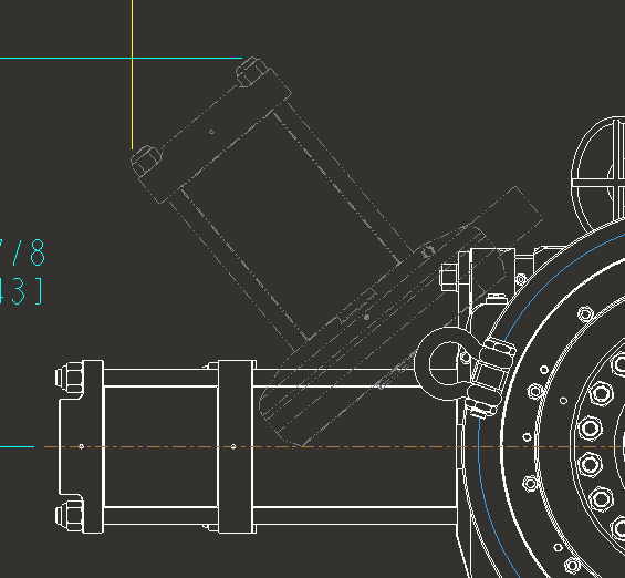
The way I do this is to make a "2D backdrop" part file to show the moving component(s). Images below are of a "door" swing of a piece of equipment. We show this on customer drawings.
The 2d part file is a simple import in to a part file of a quick drawing I made of the moved component. Takes me maybe 10 minutes or likely less to do everything.
Pros: it adds no weight to the model, it is lightweight graphically
cons: it adds a part to the model and database. you have to simp rep or blank or layer it in views or models you don't want to see it in, doesn't update to original model changes (in our case, these models don't change in size or graphics)

May 15, 2016
03:22 PM
- Mark as New
- Bookmark
- Subscribe
- Mute
- Subscribe to RSS Feed
- Permalink
- Notify Moderator
May 15, 2016
03:22 PM
I don't fully understand how you created phantom line part? Is it just exporting an assembly as a part then re import?
May 16, 2016
08:19 AM
- Mark as New
- Bookmark
- Subscribe
- Mute
- Subscribe to RSS Feed
- Permalink
- Notify Moderator
May 16, 2016
08:19 AM
I make a drawing of what I want to see, in this case the door. Export the drawing to dxf. Import the dxf to a part file.
some tips.
I export with no format
I usually move a known point of the view to 0,0 of the drawing so when it imports backs in to the part file with that at the coord sys
I sometimes make a new coord sys in the part with an offset or a angle change so I can control the import orientation
I use the MODEL TAB-GET DATA-IMPORT instead of importing in to the sketcher (sketcher intent manager can make that a disaster)
May 28, 2016
02:28 PM
- Mark as New
- Bookmark
- Subscribe
- Mute
- Subscribe to RSS Feed
- Permalink
- Notify Moderator
May 28, 2016
02:28 PM
Ok, I like this idea, but at the same time, I don't. Because I like things parametric. Like a few days ago, I did the export/import and my customer just asked for screenshots (not 2d, yet). But NOW that I have updated the design and they want the exploded version on 2D and I have ot do it all again (one way or another).
I am sort of frustrated with this at the moment. I might even just do it in whatever autocad clone I have.
Thanks for the input.
May 28, 2016
03:56 PM
- Mark as New
- Bookmark
- Subscribe
- Mute
- Subscribe to RSS Feed
- Permalink
- Notify Moderator
May 28, 2016
03:56 PM
If the example of an overlay is what you want, create a drawing-specific assembly with the base assembly you like and reassemble the moving parts into it. They can have the component display set to phantom.
