
Turn on suggestions
Auto-suggest helps you quickly narrow down your search results by suggesting possible matches as you type.
Showing results for
Turn on suggestions
Auto-suggest helps you quickly narrow down your search results by suggesting possible matches as you type.
Showing results for
Community Tip - Visit the PTCooler (the community lounge) to get to know your fellow community members and check out some of Dale's Friday Humor posts! X
- Community
- Creo+ and Creo Parametric
- 3D Part & Assembly Design
- Re: How to Change Parameter and or Dimension in Mo...
Options
- Subscribe to RSS Feed
- Mark Topic as New
- Mark Topic as Read
- Float this Topic for Current User
- Bookmark
- Subscribe
- Mute
- Printer Friendly Page
How to Change Parameter and or Dimension in Model for Only One View without using a Family Table?
Sep 01, 2016
09:40 AM
- Mark as New
- Bookmark
- Subscribe
- Mute
- Subscribe to RSS Feed
- Permalink
- Notify Moderator
Sep 01, 2016
09:40 AM
How to Change Parameter and or Dimension in Model for Only One View without using a Family Table?
Good Morning,
Would anyone know how to change a model Parameter (and or Dimension) and only have it effect the model in one view on a drawing?
I have a part that has 2 pins that are staked during assembly and would like to show the installed state options on the component drawing as additional views.
The alternate states of the part are built into the model and controlled using a parameter to specify what state to show. Placing the part in the assembly using Flexibility, one's able to set the parameter for each placement of the component. I would like to do the same thing in the component drawing to show the alternate installed states.
I've looked at drawing parameters tied to the model parameters, but this changes the model in all views from what I can tell.
With Part reps one needs to have all of the installed states modeled so one can turn them on and off using simplified reps.
Family tables create extra work in a PDM revision controlled environment and other issues.
Not sure if relations can be related so they just effect the model shown in just one drawing view.
Any Ideas?
Thanks,
Don Anderson
This thread is inactive and closed by the PTC Community Management Team. If you would like to provide a reply and re-open this thread, please notify the moderator and reference the thread. You may also use "Start a topic" button to ask a new question. Please be sure to include what version of the PTC product you are using so another community member knowledgeable about your version may be able to assist.
6 REPLIES 6
Sep 01, 2016
01:37 PM
- Mark as New
- Bookmark
- Subscribe
- Mute
- Subscribe to RSS Feed
- Permalink
- Notify Moderator
Sep 01, 2016
01:37 PM
There is probably a couple of ways to do this, but in general, you cannot have drawing specific variation in the models.
I could be wrong, but I suspect this to be the case. Most things about drawings are managed in the part or assembly model.
You can use display states in drawings;
Adding a different family table instance is probably the most conventional method.
You can use explode states as a pseudo-position change (explodes can be controlled very accurately).
Layers?
I didn't quite follow your use-case but one of the above should get you there.
Sep 01, 2016
03:06 PM
- Mark as New
- Bookmark
- Subscribe
- Mute
- Subscribe to RSS Feed
- Permalink
- Notify Moderator
Sep 01, 2016
03:06 PM
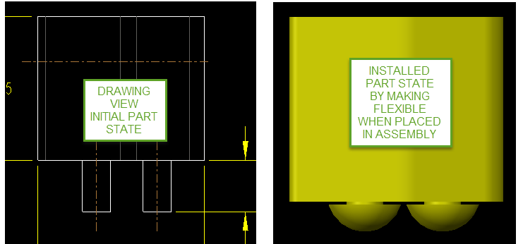
The goal is to have a part where features change shape (component installed states) and these changes are to be shown on a component level drawing without using a family table to control the part geometry. The part below has two or more states which need to be shown on the component drawing without using a family table and the default state of the part when you open it needs to have the longer pins as shown in the image on the left. Also the pins (tubular portion) needs to change length.
See Product Idea in original post above.
Hope this makes more sense.
Thanks,
Don Anderson
Sep 01, 2016
04:35 PM
- Mark as New
- Bookmark
- Subscribe
- Mute
- Subscribe to RSS Feed
- Permalink
- Notify Moderator
Sep 01, 2016
04:35 PM
I would use the simplified rep route for this.
Just make the part as it would be assembled (which is the common default state), and exclude features that mushrooms the posts for the relevant fabrication views.
Sep 01, 2016
08:52 PM
- Mark as New
- Bookmark
- Subscribe
- Mute
- Subscribe to RSS Feed
- Permalink
- Notify Moderator

Sep 12, 2016
08:52 AM
- Mark as New
- Bookmark
- Subscribe
- Mute
- Subscribe to RSS Feed
- Permalink
- Notify Moderator
Sep 12, 2016
08:52 AM
Hi Antonius,
My issue is that the component as purchased under the part number must be presented by default with the straight long pins as this is how the model must be sent to suppliers who make the part for us and the same part number needs to also be placed in the assembly to drive our production BOM's.
I also would like to show the approved staking states for the part during assembly on the drawing without creating additional part numbers as this creates items that can't be used in assemblies.
Currently I'm making the part flexible when it's brought into the assembly to turn on the desired staked feature which is driven by 2 parameters to control stake type and mating material thickness. These parameters control relations which in turn control a pro-program which swaps out the staked end types.
So no Simplified Reps are needed.
Now I would like to show these options on the component drawing.
Thanks,
Don Anderson
Sep 01, 2016
01:45 PM
- Mark as New
- Bookmark
- Subscribe
- Mute
- Subscribe to RSS Feed
- Permalink
- Notify Moderator
Sep 01, 2016
01:45 PM
You can do different flavors of this with Family Table, Simplified Representation, and Flexible Component, maybe with derived/merge/inheritance models depending on the desired result. It is intended that everything along this line needs to be defined in the solid model.
