
Turn on suggestions
Auto-suggest helps you quickly narrow down your search results by suggesting possible matches as you type.
Showing results for
Turn on suggestions
Auto-suggest helps you quickly narrow down your search results by suggesting possible matches as you type.
Showing results for
Community Tip - Did you get an answer that solved your problem? Please mark it as an Accepted Solution so others with the same problem can find the answer easily. X
- Community
- Creo+ and Creo Parametric
- 3D Part & Assembly Design
- Re: How to erase specific edges on drawing file.
Options
- Subscribe to RSS Feed
- Mark Topic as New
- Mark Topic as Read
- Float this Topic for Current User
- Bookmark
- Subscribe
- Mute
- Printer Friendly Page
How to erase specific edges on drawing file.
Jul 04, 2014
11:36 PM
- Mark as New
- Bookmark
- Subscribe
- Mute
- Subscribe to RSS Feed
- Permalink
- Notify Moderator
Jul 04, 2014
11:36 PM
How to erase specific edges on drawing file.
I want to remove specific edges in the drawing file on a section view but not able to do so.
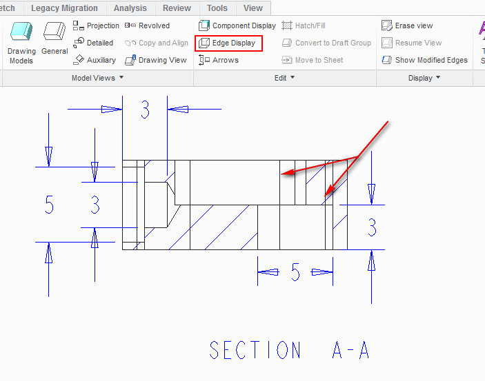
I tried Edge Display Tool but it is not working. How it is possibe please help me in this regard.
Regards
Nisheeth.
This thread is inactive and closed by the PTC Community Management Team. If you would like to provide a reply and re-open this thread, please notify the moderator and reference the thread. You may also use "Start a topic" button to ask a new question. Please be sure to include what version of the PTC product you are using so another community member knowledgeable about your version may be able to assist.
Solved! Go to Solution.
Labels:
- Labels:
-
2D Drawing
1 ACCEPTED SOLUTION
Accepted Solutions
Jul 05, 2014
03:59 AM
- Mark as New
- Bookmark
- Subscribe
- Mute
- Subscribe to RSS Feed
- Permalink
- Notify Moderator
11 REPLIES 11
Jul 05, 2014
12:35 AM
- Mark as New
- Bookmark
- Subscribe
- Mute
- Subscribe to RSS Feed
- Permalink
- Notify Moderator
Jul 05, 2014
12:35 AM
share the model...
Jul 05, 2014
01:59 AM
- Mark as New
- Bookmark
- Subscribe
- Mute
- Subscribe to RSS Feed
- Permalink
- Notify Moderator
Jul 05, 2014
01:59 AM
Those are probably not edges. Section A-A must be a offset section. These are the division lines for where the offset jogs. I haven't found a way to control these.
Jul 05, 2014
03:03 AM
- Mark as New
- Bookmark
- Subscribe
- Mute
- Subscribe to RSS Feed
- Permalink
- Notify Moderator
Jul 05, 2014
03:03 AM
When I Select from pick from the list it says Surface F12 Extrude 4. Check the image.
It means we can not use Edge Display command to clean any specific line, so for what it is meant for.
In Autodesk Inventor any line can be selected and turned off its visiblity on the right click context menu and change of colour as well. I was trying to find similar function.
Jul 05, 2014
03:35 AM
- Mark as New
- Bookmark
- Subscribe
- Mute
- Subscribe to RSS Feed
- Permalink
- Notify Moderator
Jul 05, 2014
03:35 AM
Jul 05, 2014
03:42 AM
- Mark as New
- Bookmark
- Subscribe
- Mute
- Subscribe to RSS Feed
- Permalink
- Notify Moderator
Jul 05, 2014
03:42 AM
That is nice but you did not told the way just posted the finished result.
Jul 05, 2014
03:45 AM
- Mark as New
- Bookmark
- Subscribe
- Mute
- Subscribe to RSS Feed
- Permalink
- Notify Moderator
Jul 05, 2014
03:59 AM
- Mark as New
- Bookmark
- Subscribe
- Mute
- Subscribe to RSS Feed
- Permalink
- Notify Moderator
Jul 05, 2014
03:59 AM
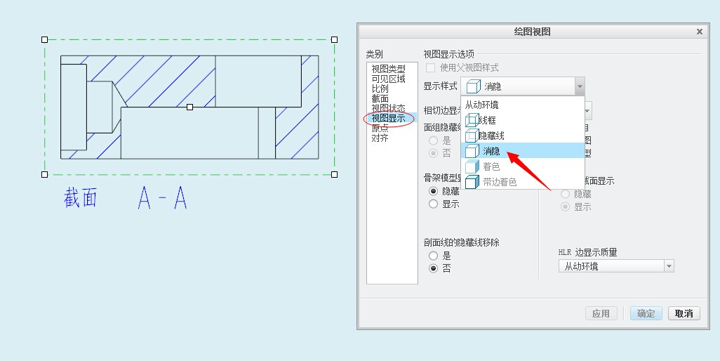 I think you should check it here
Jul 05, 2014
08:05 AM
- Mark as New
- Bookmark
- Subscribe
- Mute
- Subscribe to RSS Feed
- Permalink
- Notify Moderator
Jul 05, 2014
08:05 AM
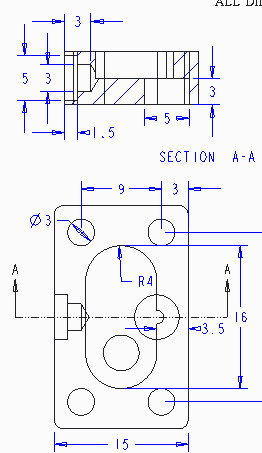
Thanks a lot quite a useful response, I was able to follow it easily. One more question I want to ask which tool is used to place centre mark and centre line representation in drawing sheet as you have showen in your image.
Jul 05, 2014
10:41 AM
- Mark as New
- Bookmark
- Subscribe
- Mute
- Subscribe to RSS Feed
- Permalink
- Notify Moderator
Jul 05, 2014
10:41 AM
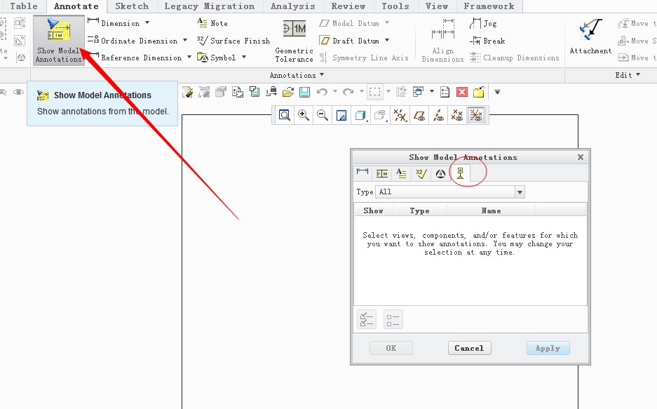 It seems that you are not familiar with creo drawing.I can tell you anything that I know(Creo)
Jul 05, 2014
01:55 PM
- Mark as New
- Bookmark
- Subscribe
- Mute
- Subscribe to RSS Feed
- Permalink
- Notify Moderator
Jul 05, 2014
01:55 PM
You are correct. With your help I could do what I wanted. Well thanks again.
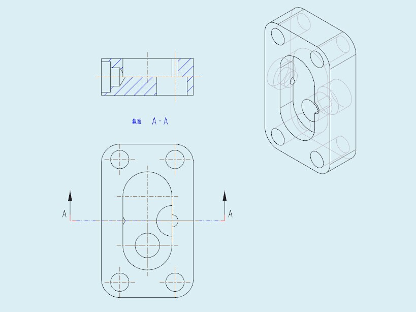
A attachment was uploaded by you what was that for.
Jul 05, 2014
02:04 PM
- Mark as New
- Bookmark
- Subscribe
- Mute
- Subscribe to RSS Feed
- Permalink
- Notify Moderator
Jul 05, 2014
02:04 PM
Good eye, Blue. I didn't notice that these were the holes in wireframe mode.
